1. Introduction to Raspberry Pi
(1) Raspberry Pi
Raspberry Pi (Raspberry Pi, RasPi/RPi) is developed by the British charity organization "Raspberry Pi Foundation", based on ARM microcomputer motherboard, only the size of a credit card, but has the basic functions of a personal computer. The original purpose of the Foundation’s development of the Raspberry Pi was to improve the teaching level of the school’s computer science and related disciplines, and cultivate the youth’s computer programming interest and ability. Nowadays, most people use the Raspberry Pi for embedded development, which is mostly used in the Internet of Things, smart home and artificial intelligence.
(2) Raspberry Pi motherboard
In our lessons, we will use the Raspberry Pi 4 motherboard. Let's take a look at the structure of the Raspberry Pi 4 motherboard. As shown in the following figure:
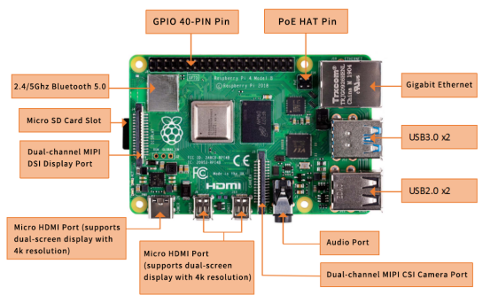
The following contents will briefly explain the main structure ports of the Raspberry Pi 4 motherboard:
(1) GPIO 40-PIN pin:
The General Purpose Input Output (GPIO) is designed as a slot with two rows of pins on the Raspberry Pi motherboard. GPIO can be used to connect various peripheral electronic devices and sensors to control or monitor these devices through input/output level signals. For example, you can use GPIO to control the speed of a DC motor, or read the measured distance of an ultrasonic sensor. These functional characteristics of GPIO make the Raspberry Pi different from ordinary computer motherboards because it gives developers the freedom to operate manually. We will further introduce GPIO in the subsequent chapters and use them extensively.
(2) Gigabit Ethernet port:
The Ethernet interface allows the Raspberry Pi to connect to the computer network in a wired manner, which allows us to easily access the Internet or log in to the Raspberry Pi remotely. The Raspberry Pi's Ethernet interface is implemented using a USB bus, and data is transferred through the USB bus. Most models of Raspberry Pi provide an Ethernet interface
(3) Micro HDMI port:
High-definition multimedia interface (High Definition Multimedia Interface, HDMI) is a fully digital video and sound transmission interface, used to transmit uncompressed audio and video signals. By connecting it to a display (or TV) equipped with an HDMI interface, the content of the Raspberry Pi can be displayed. The HDMI interface can transmit video and audio signals at the same time, so when we use it, we don't need to connect speakers to the audio interface of the Raspberry Pi. If we really need to play sound through the audio interface, we need to modify the operating system configuration accordingly.
(4) USB2.0/3.0 port:
The Universal Serial Bus (USB) interface is the most common interface on a computer. You can use it to connect devices such as keyboards, mice, USB flash drives, and wireless network cards. When the number of USB ports is not enough, we can also increase the number of USB ports through a USB hub.
(5) Audio port:
Audio interface (3.5mm headphone jack) When HDMI connection is not used, you can use the standard 3.5mm headphone jack speakers or headphones to play audio. At the same time, the interface also integrates a composite video interface with a composite audio and video output function, which is generally used to connect to old models of TVs, and is currently rarely used.
(6) MIPI CSI camera port:
The CSI interface can be used to connect the CSI camera to the Raspberry Pi via a ribbon cable for easy video recording and image capture. Compared with the USB camera, this camera module has better performance.
(7) USB-C 5V/3A power supply port:
The Micro USB power supply interface is one of the main power supply methods of the Raspberry Pi. The rated voltage is 5V. The standard current requirements of different versions of the Raspberry Pi are slightly different. For example: the 1B type only needs 700mA, and the 3B+ type requires 2.5A. The chargers of many Android mobile phones can provide the necessary voltage and current for the Raspberry Pi. The current demand of the Raspberry Pi is also related to the connected external device. It is recommended that it should be calculated in advance when using it. Choose a suitable current (power) power supply for the Raspberry Pi. When the external device has a large power, an independent power supply should be used Power supply for external devices.
(8) Micro SD card slot:
The SD card slot is located on the back of the Raspberry Pi motherboard. The SD/MicroSD card is an essential storage part of the Raspberry Pi. It is used to install the operating system and store data. The capacity of the SD card should be above 2GB. In order to have a better experience, it is recommended to equip your Raspberry Pi with a large-capacity (above 16G) high-speed (Class10 or above) SD card.
(9) Bluetooth port:
The Bluetooth function allows the Raspberry Pi to connect with Bluetooth-enabled devices (such as a mouse, keyboard, and handle).
(10) PoE HAT port:
Active Ethernet (Power Over Ethernet, PoE) refers to a technology that uses Ethernet for power transmission. On the basis of the original Micro USB and GPIO power supply, the Raspberry Pi 3B+ type adds a new power supply method over Ethernet. Users can use the network cable to supply power to the Raspberry Pi without the need to configure an additional power supply, which is convenient for certain application scenarios.
(11) MIPI DSI display port:
You can connect the LCD display to the Raspberry Pi, which is generally used for embedded product development. Under normal circumstances, the HDMI interface can already meet the demand.
(3)Operating system
The Raspberry Pi supports a variety of operating systems, mainly based on Liunx and Windows, and most of them can be found on the official website of the Raspberry Pi Foundation (www.raspberrypi.org). The following briefly introduces two representative operating systems.
(1) Raspbian
Raspbian is the official operating system of the Raspberry Pi Foundation. It is customized based on Debian GNU/Linux and can run on all versions of the Raspberry Pi motherboard. According to the experience, Raspbian and Raspberry Pi combine the best, stable operation, powerful, easy to use, can basically meet various application needs, so it is strongly recommended to use Raspbian as the preferred operating system for Raspberry Pi. In the following chapters, we will further introduce the use of Raspbian in detail, and develop various applications on it.
(2) Windows 10 IoT Core
Windows 10 IoT Core is an operating system specifically created by Microsoft for the Internet of Things ecosystem. Windows 10 IoT Core is the core version of the Windows 10 IoT operating system. It has relatively simple functions and can run on the Raspberry Pi of type 2B or above. The installation and use of Windows 10 IoT Core will not be described in detail here. If you are interested, you can visit Microsoft's website for more information.
In addition to the two operating systems described above, there are several operating systems that support the Raspberry Pi, such as Ubuntu MATE, OSMC, LibreELEC, PiNet, RISC OS, etc. As for which one to choose, it depends on whether you want to use Raspberry What to do. If you want to use the Raspberry Pi as an ordinary computer or for electronic project development, then Raspbian is a very good choice. If you plan to use the Raspberry Pi as a media center, you can consider using OSMC or LibreELEC.
(4)Programming language
For the Raspberry Pi, there are many programming languages available. In fact, any language that can be compiled for the ARM architecture (such as the C language) can be used for the Raspberry Pi. The most popular language should be Python. In fact, the Pi in the name of the Raspberry Pi was inspired by the word Python. Python is an interpretive, object-oriented, and dynamic data type high-level programming language with powerful functions, good compatibility, and high reliability. Python programs are easy to write and read. At present, there are two major versions of Python: Python 2 and Python 3. Both versions have been updated and maintained, but people still have disputes about which version to use. You can visit Python's official website (www.python.org) to understand more related content, in the future we will mainly use Python 3 for development introduction. In addition, because the compatibility of the Raspberry Pi is splendid, the program we wrote on the 3B+ model can be run on the Zero W model with little modification.
2. Introduction to GPIO
(1) What is GPIO
A powerful feature of the Raspberry Pi is the row of GPIO (general-purpose input/output) pins along the top edge of the board. A 40-pin GPIO header is found on all current Raspberry Pi boards (unpopulated on Pi Zero and Pi Zero W). Prior to the Pi 1 Model B+ (2014), boards comprised a shorter 26-pin header.
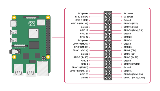
Any of the GPIO pins can be designated (in software) as an input or output pin and used for a wide range of purposes.
【Note】:
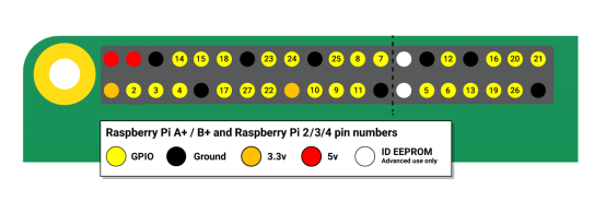
The numbering of the GPIO pins is not in numerical order; GPIO pins 0 and 1 are present on the board (physical pins 27 and 28) but are reserved for advanced use (see below).
Voltages
Two 5V pins and two 3V3 pins are present on the board, as well as a number of ground pins (0V), which are unconfigurable. The remaining pins are all general purpose 3V3 pins, meaning outputs are set to 3V3 and inputs are 3V3-tolerant.
Outputs
A GPIO pin designated as an output pin can be set to high (3V3) or low (0V).
Inputs
A GPIO pin designated as an input pin can be read as high (3V3) or low (0V). This is made easier with the use of internal pull-up or pull-down resistors. Pins GPIO2 and GPIO3 have fixed pull-up resistors, but for other pins this can be configured in software.
More
As well as simple input and output devices, the GPIO pins can be used with a variety of alternative functions, some are available on all pins, others on specific pins.
-PWM (pulse-width modulation)
-Software PWM available on all pins
-Hardware PWM available on GPIO12, GPIO13, GPIO18, GPIO19
-SPI
-SPI0: MOSI (GPIO10); MISO (GPIO9); SCLK (GPIO11); CE0 (GPIO8), CE1 (GPIO7)
-SPI1: MOSI (GPIO20); MISO (GPIO19); SCLK (GPIO21); CE0 (GPIO18); CE1 (GPIO17); CE2 (GPIO16)
-I2C
-Data: (GPIO2); Clock (GPIO3)
-EEPROM Data: (GPIO0); EEPROM Clock (GPIO1)
-Serial
-TX (GPIO14); RX (GPIO15)
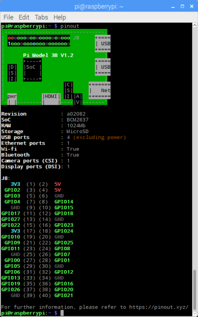
GPIO pinout
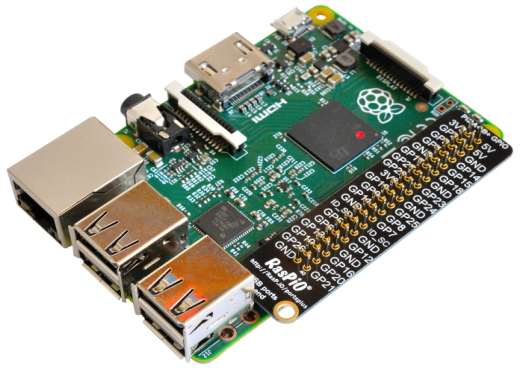
It's important to be aware of which pin is which. Some people use pin labels (like the RasPiO Portsplus PCB, or the printable Raspberry Leaf).
A handy reference can be accessed on the Raspberry Pi by opening a terminal window and running the command pinout. This tool is provided by the GPIO Zero Python library, which it is installed by default on the Raspberry Pi OS desktop image, but not on Raspberry Pi OS Lite.
For more details on the advanced capabilities of the GPIO pins see gadgetoid's interactive pinout diagram.
(2) Introduction of GPIO pins
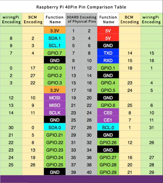
GPIO pin comparison table:
【Form description】:
(1) Three naming (coding) methods for Raspberry Pi pins
Three ways to name the Raspberry Pi pins:
The WiringPi number is the pin number of the functional wiring (such as TXD, PWM0, etc.); the BCM number is the Broadcom pin number, also known as GPIO; the physical number is the number corresponding to the physical location of the pin on the Raspberry Pi motherboard (1 ~40).
(2) 3.3V/5V pin and GND pin
3.3V/5V pin and GND pin are commonly known as power and ground pins. The power and ground pins allow your Raspberry Pi to power some external components, such as LED lights. It should be noted that before using these pins to power any external modules or components, care should be taken. Excessive operating current or peak voltage may damage the Raspberry Pi. Do not use voltages greater than 5V.
(3) SDA and SCL pins
The SDA and SCL pins constitute the I2C interface. I2C is a simple, bidirectional two-wire synchronous serial bus developed by Philips. It only requires two wires to transfer information between devices connected to the bus. The Raspberry Pi can control multiple sensors and components through the I2C interface. Their communication is done through SDA (data pin) and SCL (clock speed pin). Each slave device has a unique address, allowing rapid communication with many devices. The ID_EEPROM pin is also an I2C protocol, which is used to communicate with HATs.
(4) SCLK, MOSI and MISO pins
SCLK, MOSI and MISO pins form the SPI interface. SPI is a serial peripheral interface, used to control components with a master-slave relationship, and works in a slave-in, master-out and master-in-slave manner. The SPI on the Raspberry Pi consists of SCLK, MOSI, and MISO interfaces, and SCLK is used for controlling data speed, MOSI sends data from the Raspberry Pi to the connected device, while MISO does the opposite.
(5) TXD and RXD pins
TXD and RXD form a UART interface. TXD is a pin to send data, and RXD is a pin to receive data. A friend who uses Arduino must have heard of UART or Serial. The Universal Asynchronous Receiver/Transmitter interface is used to connect the Arduino to the computer for which it is programmed. It is also used for communication between other devices and the RX and TX pins. If the Raspberry Pi has a serial terminal enabled in raspi-config, you can use these pins to control the Raspberry Pi through a computer or directly to control the Arduino.