In this lesson, we will learn how to control LED with Raspberry Pi.
2.1 Components used in this course
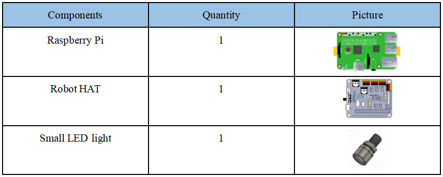
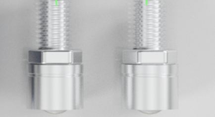
2.2 Introduction of small warm color LED
The small warm color LED is a LED that can emit warm white light after being lit. It has a working power of 0.5W, a working voltage of 5V/12V, and a light-emitting angle of 60°. The red line represents the positive pole and the black line represents the negative pole. The small LED needs to be connected to Port1, Port2, and Port3 on the Robot HAT driver board to use
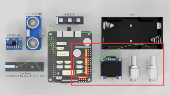
2.3 Wiring diagram (Circuit diagram)
When the small warm color LED is used, it needs to be connected to the Port1, Port2, and Port3 on the Robot HAT driver board, as shown in the red box:
2.4 How to control the small warm color LED
2.4.1Run the program of this course
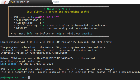
1. Open the terminal software MobaXterm:

2. Log in to your Raspberry Pi (the way to log in to Raspberry Pi has been introduced in Lesson 1):
3. Enter the Course Code folder, this folder stores the sample code program to control the robot, enter the following command:
cd adeept_alter/02CourseCode

4. Enter the command to display the contents of the current directory:
ls

5. The 01ComponentCode folder stores the sample code of this course. Enter the command to enter this folder:
cd 01ComponentCode

6. Enter the command to display the contents of the current directory:
ls

7. The 01LED file is the sample code program of this lesson. You need to enter this file before you can run this control program. Enter the command:
cd 01LED

8. LED.py is a python program.You can run this program on the Raspberry Pi by directly by typing the following commands:
sudo python3 LED.py

9. After successfully running the program, you will observe that the small warm color LED will light up.
10. If you want to terminate the running program, you can press the shortcut key Ctrl+C on the keyboard.
2.4.2 The main code program of this lesson
After the above hands-on practice, you already know how to use and run our course sample code program. You must be curious about how our code program is programmed to control the LED on the Raspberry Pi. Let’s get to know the main code program.
2.4.2.1 View and edit the code of this lesson
To view and edit our code program on Sublime IDE terminal software, we provide two methods for reference.
The first is to use Linux commands. For example, if you need to view the code program LED.py of this section of the course, then you can enter the following commands in the console of the MobaXterm terminal:
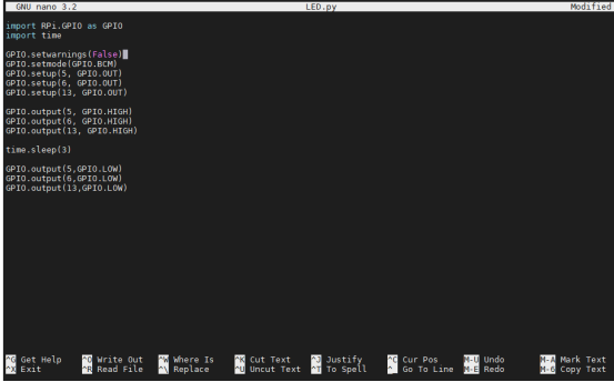
sudo nano LED.py

In this way, we can view the code program. You can modify and edit the code through the direction keys on the keyboard to realize the control function you want. But you need to learn and search about the command operation method of Linux nano. Here we provide several common operation commands about nano:
1. To save the modified program, you need to press the shortcut key Ctrl+O on the keyboard
2. To exit the program code interface, you need to press the shortcut key Ctrl+X on the keyboard
3. To cut a line of code, you can use Ctrl+K
4. To paste the code, you can use Ctrl+U
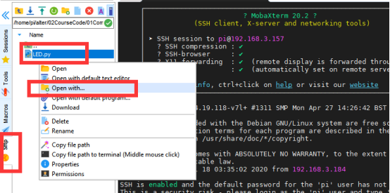
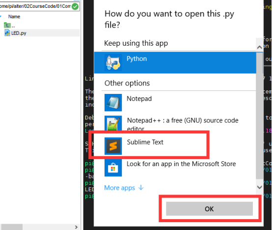
The second method is to use a third-party IDE tool to view and edit the code program of this lesson. You can find the file you want to edit in the file resource management system on the left of MobaXterm, right-click the file, and click Open with , choose your IDE, we recommend you to use Sublime Text IDE, you need to download it from: http://www.sublimetext.com/3, so that you can use the IDE you want to edit the files in the Raspberry Pi. After editing, CTRL+S can save the files.
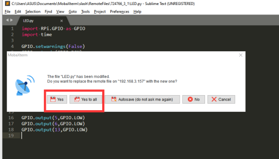
If you need to save the modified file, you can press the shortcut key CTRL+S, and then select Yes or Yes to all.
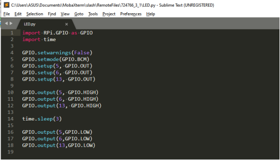
2.4.2.2 Study the main code program of this lesson
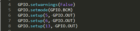
1. First import the library used to control the Raspberry Pi GPIO, and instantiate it as a GPIO while importing it.

2. Then set the Port1, Port2, and Port3 interfaces to the corresponding GPIO pin numbers 5, 6, and 13 of the Raspberry Pi. Here we use BCM coding.
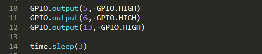
3. Turn on the Port1, Port2, and Port3 ports respectively. At this time, the small warm color LED will light up for 3s. If you want the LED to stay on for a longer time, you only need to change the number 3 of sleep(3) to other numbers.
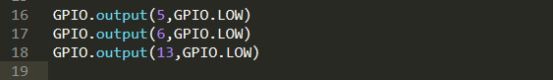
4.After 3s, turn off the Port1, Port2, and Port3 interfaces, and then the small warm color LED connected to the Port interface will go out.
2.5 How to control the LED on Robot HAT driver board
When you study the content of this course, even if you do not use the Small LED module, you can also learn this lesson by controlling the LED on the Robot HAT driver board,because there is a green LED next to each interface: when the interface is turned on, the LED next to the interface will light up, indicating that the interface is on.
You can observe the status of the LED on the Robot HAT driver board by using the method of "2.4 How to control the small warm color LED " above.