In this lesson, we will learn how to control WS2812 LED.
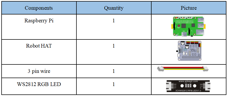
5.1 Components used in this course
5.2 Introduction of WS2812 RGB LED
WS2812 RGB module is a low-power RGB tri-color lamp with integrated current control chip. Its appearance is the same as a 5050LED lamp bead, and each element is a pixel. The pixel contains an intelligent digital interface data latch signal shaping amplifier driving circuit, and also contains a high-precision internal oscillator and a 12V high-voltage programmable constant current control part, which effectively guarantees that the color of the pixel light is highly consistent.
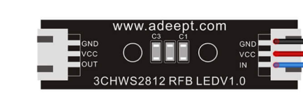
WS2812 LED is a very commonly used module on our robot products. There are three WS2812 LEDS on each module. Pay attention to the direction of the signal line when connecting. The signal line needs to be connected to the “IN” port of WS2812 LED after being led from the Raspberry Pi. When the next WS2812 LED needs to be connected, we connect a signal wire drawn from the "OUT" port of the previous WS2812 LED with the "IN" port of the next WS2812 LED.
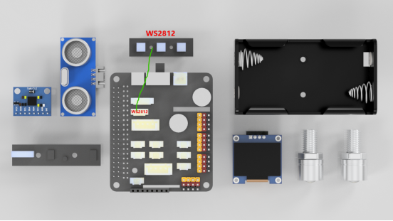
When using the Raspberry Pi to install the driver board RobotHAT, the WS2812 LED can be connected to the WS2812 interface on the RobotHAT using a 3pin cable.
We use a third-party library [rpi_ws281x] to control the WS2812 LED. You can learn about it via:
https://github.com/richardghirst/rpi_ws281x
If you connect the WS2812 LED to the WS2812 interface of RobotHAT, the signal line is equivalent to connecting to the GPIO 12 of the Raspberry Pi.
5.3 Wiring diagram (Circuit diagram)
When the WS2812 LED is in use, the IN port needs to be connected to the WS2812 port on the RobotHAT driver board, as shown in the figure below:
5.4 How to control WS2812 LED
5.4.1Run the program of this course
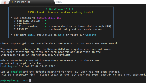
1. Open the terminal software MobaXterm:

2. Log in to your Raspberry Pi (the way to log in to Raspberry Pi has been introduced in Lesson 1):
3. Enter the Course Code folder, this folder stores the sample code program to control the robot, enter the following command:
cd adeept_alter/02CourseCode/01ComponentCode

4. Enter the command to display the contents of the current directory:
ls

5. The 04WS2812 folder stores the sample code of this course. Enter the command to enter this folder:
cd 04WS2812

6. Enter the command to display the contents of the current directory:
ls

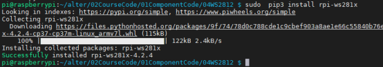
7.WS2812.py is a python program. When using the WS2812 module, we need to install the Python dependency library needed to control the WS2812 module. Enter the following command in the console of the command window:
sudo pip3 install rpi-ws281x
8.WS2812.py is a python program.You can run this program on the Raspberry Pi by directly by typing the following commands:
sudo python3 WS2812.py
9.After running the program successfully, you will observe that the WS2812 LED is cyclically switching between red, green and blue.
10.If you want to terminate the running program, you can press the shortcut key Ctrl+C on the keyboard.
5.4.2 The main code program of this lesson
After the above hands-on operation, you already know how to use and run our course sample code program. Then you must be curious about how our code program is programmed to control WS2812 on the Raspberry Pi. Let's get to know main code program. Here we use Sublime IDE to view and edit the code program of this course. Please refer to the content of Lesson 2 for the specific method.
1. First import the library used to control WS2812.

2. Construct LED control class.
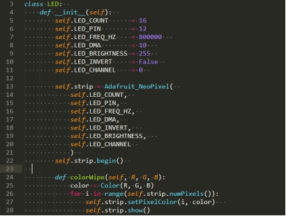
In class LED, set the total number of LEDS on the robot product with self.LED_COUNT=16.

Set as the input pin number of the LED group.

This function is used to change the color of the LED.

Only one LED color can be set at a time, so a loop is required.

After calling the show() method, the color will actually be changed.

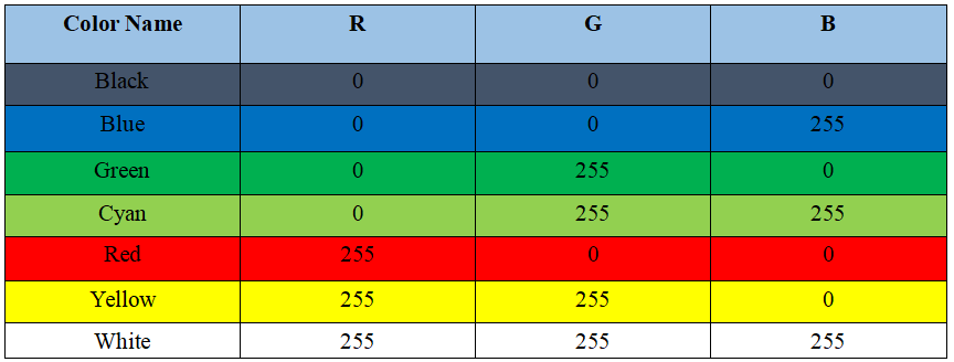
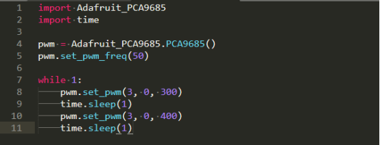
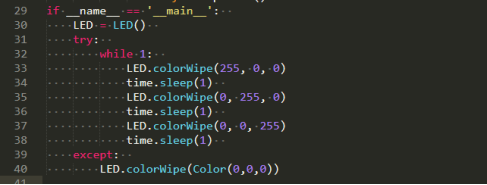
3.Instantiate the object and execute the method function. The function colorWipe() needs to be input three parameters, which are R, G, B, corresponding to the brightness of the three primary colors of light, red, green and blue. The value range is 0-255, the larger the value, the higher the brightness of the corresponding color channel. If the values of the three color channels are the same, white light will be emitted. The specific examples are as follows:
4. If you need to display other colors, you can modify the parameter values in the colorWire (R, G, B) method. We provide several commonly used RGB color values for reference.