In this lesson, we will learn how to display the data of MPU6050 on the OLED screen.
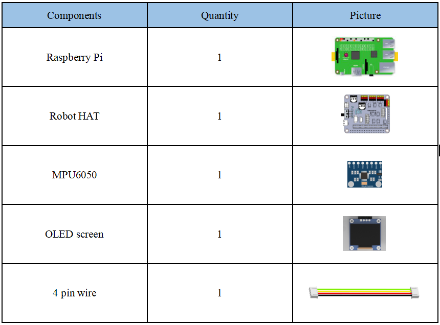
10.1 Components used in this course
10.2 The introduction of MPU6050
MPU-6050 is the world's first integrated 6-axis MotionTracking device. It integrates a 3-axis MEMS gyroscope, a 3-axis MEMS accelerometer, and a scalable digital motion processor DMP (Digital Motion Processor). We can use an I2C interface to connect a third-party digital sensor, such as a magnetometer. After expansion, it can output a 9-axis signal through its I2C or SPI interface (SPI interface is only available on MPU-6000). MPU-6050 can also connect non-inertial digital sensors through its I2C interface, such as pressure sensors.
The MPU-6050 uses three 16-bit ADCs for the gyroscope and accelerometer respectively, and it converts the analog quantity into a digital quantity that can be output. The gyroscope can measure angular velocity, and the accelerometer can measure acceleration. In order to accurately track fast and slow movements, the measurement range of the sensor is controllable. The gyro measurement range is ±250, ±500, ±1000, ±2000°/sec (dps), and the accelerometer measurement range is ±2 , ±4, ±8, ±16g (gravity acceleration).
The MPU6050 has an on-chip 1024-byte FIFO, which helps reduce system power consumption. It communicates with all device registers using 400kHz I2C interface. In addition, a temperature sensor and an oscillator with only ±1% variation in the working environment are embedded on the MPU6050 chip. And there are programmable low-pass filters.
10.3 Wiring diagram (Circuit diagram)
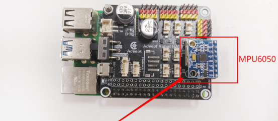
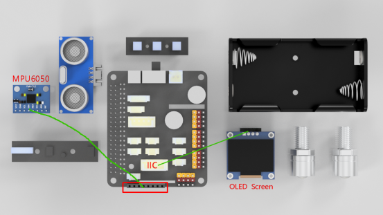
When the MPU6050 module is in use, it needs to be connected to the MPU6050 interface on the Robot HAT drive board, as shown in the figure below:
10.4 How to read the data of MPU6050
10.4.1Run the program of this course
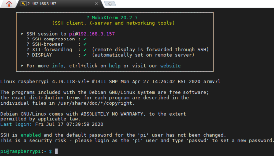
1. Open the terminal software MobaXterm:

2. Log in to your Raspberry Pi (the way to log in to Raspberry Pi has been introduced in Lesson 1):
3. Enter the Course Code folder, this folder stores the sample code program to control the robot, enter the following command:
cd adeept_alter/02CourseCode/01ComponentCode

4. Enter the command to display the contents of the current directory:
ls

5. The 09OLED_MPU6050 folder stores the sample code of this course. Enter the command to enter this folder:
cd 09OLED_MPU6050

6. Enter the command to display the contents of the current directory:
ls

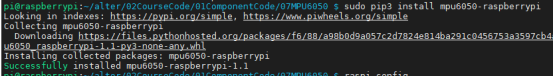
7.OLED_MPU6050.py is a python program.When using the MPU6050 module, we need to download the mpu6050-raspberrypi library and enter the following command:
sudo pip3 install mpu6050-raspberrypi
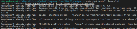
8.When using the OLED Screen module, we need to install the Python dependency library needed to control the OLED screen, called the luma.oled library, and enter the following commands in the console of the command window:
sudo pip3 install luma.oled
9. After the download is successful, we also need to start the I2C function, need to enter raspi-config to set up, and enter the following command:
sudo raspi-config

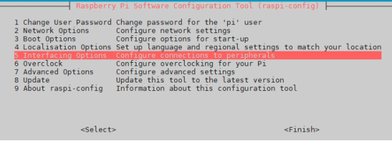
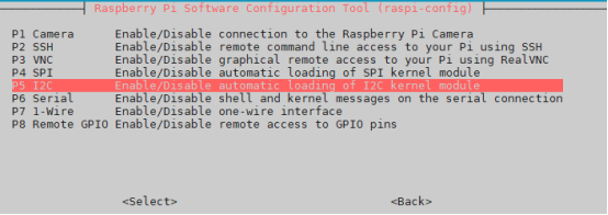
10. Press the Enter key to confirm, enter the raspi-config configuration interface as follows, we can use the up, down, left, and right keys on the keyboard to operate, by the up and down arrow keys we select the fifth item: Interfacing Options: configure the connection of peripheral devices. Select "<select>" by the left and right arrow keys and press Enter to confirm.
11. Then continue to enter the "Interfacing Options" interface, we select the fifth item "P5 I2C", select "<select>" with the left and right arrow keys, and press Enter to confirm.
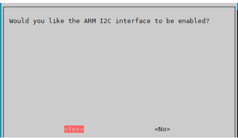
12. Then the options in the figure below will pop up, we select "<Yes>" with the left and right arrow keys:
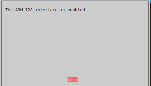
13. Select "<Yes>", press Enter to confirm, an option box will pop up, continue to press Enter to confirm:
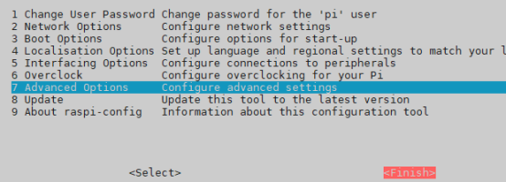
14. After confirming, it will jump back to the main interface. We select "<Finish>" with the left and right arrow keys, and press the enter key to confirm. At this time, then we will return to the command window after completing the settings.
15. Directly enter the following commands to run OLED_MPU6050.py on the Raspberry Pi:
sudo python3 OLED_MPU6050.py

16. After running the program successfully, you will observe some data on the OLED screen. The data from up to down are the data of the X, Y, and Z axis of the MPU6050 sensor.
17. When you want to terminate the running program, you can press the shortcut key Ctrl+C on the keyboard.
10.4.2 The main code program of this lesson
After the above hands-on practice, you already know how to use and run our course sample code program. You must be curious about how our code program is programmed to read the data of MPU6050 on OLED screen on the Raspberry Pi. Let’s get to know the main code program.Here we use Sublime IDE to view and edit the code program of this lesson, please refer to the content of lesson 2 for specific methods.
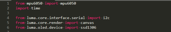
1. Import MPU6050 and the library used to control the OLED screen.
2. Obtain data from MPU6050 sensor.

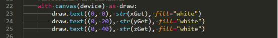
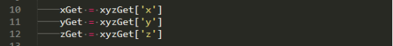
3. Read the data of X, Y, Z axis respectively.
4. Display the acquired X, Y, Z axis data on the OLED screen.