In this lesson, we will learn how to use posture sensor.
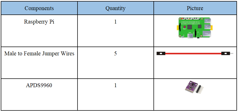
16.1 Components used in this course
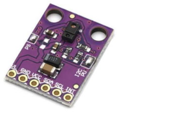
16.2 Introduction to APDS9960
The APDS-9960 device features advanced Gesture detection, Proximity detection, Digital Ambient Light Sense (ALS) and Color Sense (RGBC). The slim modular package, L 3.94 x W 2.36 x H 1.35 mm, incorporates an IR LED and factory calibrated LED driver for drop-in compatibility with existing footprints.
Gesture detection:
Gesture detection utilizes four directional photodiodes to sense reflected IR energy (sourced by the integrated LED) to convert physical motion information (i.e. velocity, direction and distance) to a digital information. The architecture of the gesture engine features automatic activation (based on Proximity engine results), ambient light subtraction, cross-talk cancelation, dual 8-bit data converters, power saving inter-conversion delay, 32-dataset FIFO, and interrupt driven I2C communication. The gesture engine accommodates a wide range of mobile device gesturing requirements: simple UP-DOWN-RIGHT-LEFT gestures or more complex gestures can be accurately sensed. Power consumption and noise are minimized with adjustable IR LED timing.
Proximity detection:
The Proximity detection feature provides distance measurement (E.g. mobile device screen to user’s ear) by photodiode detection of reflected IR energy (sourced by the integrated LED). Detect/release events are interrupt driven, and occur whenever proximity result crosses upper and/or lower threshold settings. The proximity engine features offset adjustment registers to compensate for system offset caused by unwanted IR energy reflections appearing at the sensor. The IR LED intensity is factory trimmed to eliminate the need for end-equipment calibration due to component variations. Proximity results are further improved by automatic ambient light subtraction.
Color and ALS detection:
The Color and ALS detection feature provides red, green, blue and clear light intensity data. Each of the R, G, B, C channels have a UV and IR blocking filter and a dedicated data converter producing16-bit data simultaneously. This architecture allows applications to accurately measure ambient light and sense color which enables devices to calculate color temperature and control display backlight.
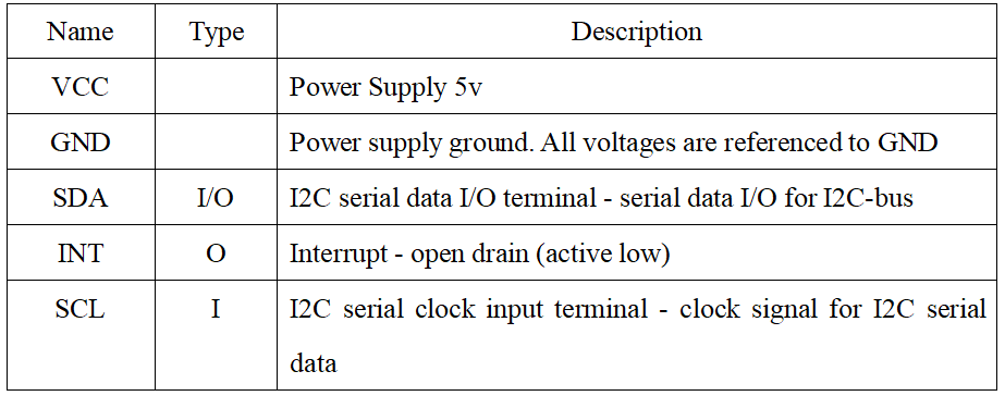
APDS9960 Pins:
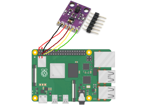
16.3 Wiring diagram (Circuit diagram)
When the APDS9960 sensor is connected to the circuit, it needs to be directly connected to the driver board of the Raspberry Pi. The VCC of the APDS9960 sensor is connected to the 5V interface (physical pin number 2) on the Raspberry Pi, and the GND is connected to the GND interface of the Raspberry Pi (Physical pin number 6), SCL is connected to the SCL interface on the Raspberry Pi (physical pin number 5), SDA is connected to the SDA interface on the Raspberry Pi (physical pin number 3), INT is connected to the physical pin 16 interface on the Raspberry Pi. As shown below:
16.4 The main code program of this lesson
We use the following code to control the APDS9960 sensor. Here, we use Subline IDE to view and edit the code program of this lesson. Please see the content of lesson 2 for specific methods. The specific code and comments are as follows:
In the file manager of the MobaXterm terminal, find the directory:
alter/02CourseCode/01ComponentCode/15APDS9960
And open the code of this lesson: apds.py.
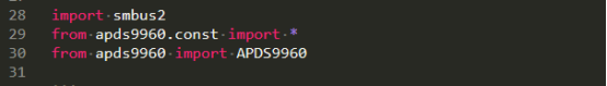
Import the library that controls apds9960.
I2C communication of apds9960, if the wire is not connected or the connection is wrong, an error will be reported.
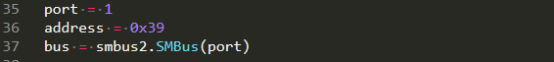
Instantiate objects.

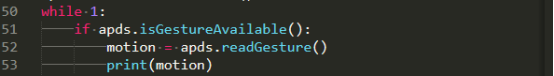
Start reading gesture information.

There are 5 return values of apds.readGesture(), including from left to right, from right to left, from top to bottom, from bottom to top, from near to far. They are replaced by numbers 1 2 3 4 5, and the placement of the sensor determines that which number corresponds to which gesture.
16.5 Run the program of this course
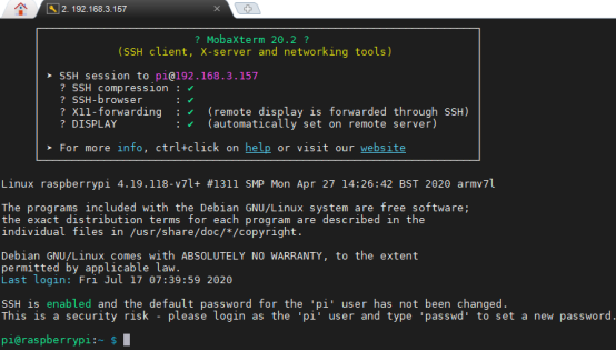
1. Open the terminal software MobaXterm:

2. Log in to your Raspberry Pi (the way to log in to Raspberry Pi has been introduced in Lesson 1):
3. Enter the Course Code folder, this folder stores the sample code program to control the robot, enter the following command:
cd adeept_alter/02CourseCode/01ComponentCode

4. Enter the command to display the contents of the current directory:
ls

5. Enter the directory where the code program files of this lesson are stored: 15APDS9960, you need to enter the following command:
cd 15APDS9960

6.When using the APDS9960 sensor, we need to install the Python dependency library needed to control APDS9960: apds9960, and enter the following command in the console of the command window:
sudo pip3 install apds9960

7. Also need to modify the I2C rate. Enter the following command to modify:
sudo nano /boot/config.txt

After opening the interface, it is as follows:
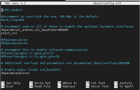
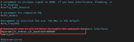
8. You need to check if there is a piece of code inside: dtparam=i2c_arm=on (white font), if there is, add a piece of new code at the end: i2c_baudrate=400000. As shown below:
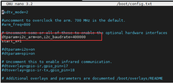
If there is no code: dtparam=i2c_arm=on (white font), then you need to add the following line of code yourself:
dtparam=i2c_arm=on,i2c_baudrate=400000
Finally press Ctrl+X to exit the editing, the system will ask you whether you agree to save the changes, enter the letter ‘Y’, and press Enter to exit.
9. Enter the command to view the contents of the current directory:
ls

10.apds.py is the sample code for this lesson, enter the command to run this program:
sudo python3 apds.py
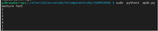
11. After running the program successfully, you can test it by swiping gestures on the APDS9960 sensor.