In this lesson, we will learn how to read the data of the RGB ultrasonic ranging module.
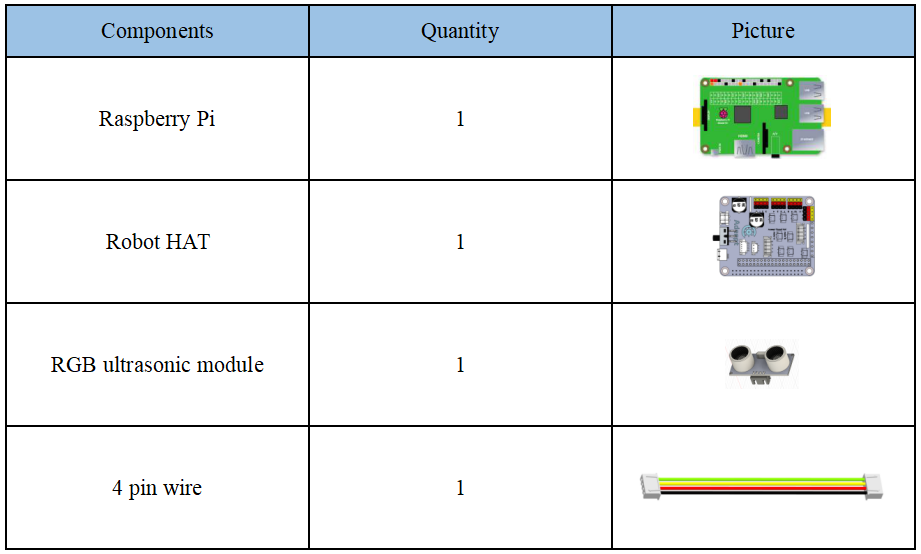
17.1 Components used in this course
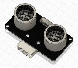
17.2 Introduction of RGB ultrasonic ranging module
Since the camera used by our Raspberry Pi robot is a monocular camera and cannot collect depth information, many of our robot products use ultrasonic ranging modules to obtain depth information and detect whether there are obstacles in a certain direction to get the distance of the obstacle.
Alter series robot products are equipped with two ultrasonic modules: RGB ultrasonic module and ordinary blue ultrasonic module (HC-SR04). The default program ultra.py uses ordinary blue ultrasonic module (HC-SR04). You can use M2x8 screws to install the RGB ultrasonic module with the M2 nut. The connection method is the same as the ordinary blue ultrasonic. When using the RGB ultrasonic sensor, you need to make some settings for the code program ultra.py and change the value of the RGBultrasonic variable inside from 0 to 1. "17.4 Obtain Ultrasonic Sensor Data" will teach you how to find this file.
The model of the ultrasonic ranging module used in our robot products is HC-SR04. The HC-SR04 module has four pins, namely VCC, GND, Echo and Trig. The HC-SR04 can provide a non-contact type of 2cm-400cm distance sensing function, and the ranging accuracy is up to 3mm; the module includes ultrasonic transmitter, receiver and control circuit. The basic working principle is as follows:
Use IO port TRIG to trigger distance measurement, and give a high level signal of at least 10us.
The module automatically sends 8 40khz square waves, and automatically detects whether there is a signal return.
There is a signal return, and a high level is output with the IO port ECHO. The duration of the high level is the time from emission to return of the ultrasonic wave.
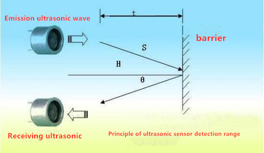
The principle of distance detection by ultrasonic ranging sensor: the method of detecting distance by ultrasonic is called echo detection method, that is, the ultrasonic transmitter emits ultrasonic waves in a certain direction, and the timer starts timing at the same time as the launch time. The ultrasonic waves propagate in the air and encounter obstacles on the way. When the object surface (object) is blocked, it will be reflected back immediately, and the ultrasonic receiver will immediately stop timing when the reflected ultrasonic wave is received. The propagation speed of ultrasonic waves in the air is 340m/s. According to the time t recorded by the timer, the distance s from the launch point to the obstacle surface can be calculated, namely: s=340t/2. Using this principle of ultrasound, the ultrasonic ranging module is widely used in practical applications, such as car reversing radar, unmanned aerial vehicle, and smart car.
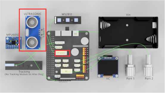
When using Robot HAT driver board, you need to connect HC-SR04 to the Ultrasonic interface on the driver board, and you must not connect it to the IIC port to avoid burning the ultrasonic module. (IIC is an interface used to connect I2C devices, and the pin positions of VCC and GND are different from Ultrasonic).
17.3 Wiring diagram (Circuit diagram)
When using Robot HAT driver board, you need to connect the ultrasonic sensor to the Ultrasonic interface on the driver board. Do not connect it to the IIC port to avoid burning the ultrasonic module. (IIC is an interface used to connect I2C devices, and the pin positions of VCC and GND are different from Ultrasonic):
17.4 Obtain data from ultrasonic sensors
17.4.1 Run the program of this course
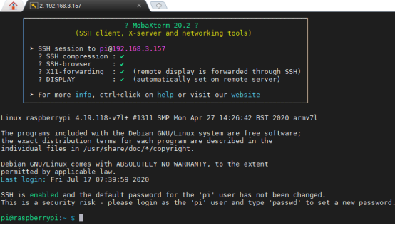
1. Open the terminal software MobaXterm:

2. Log in to your Raspberry Pi (the way to log in to Raspberry Pi has been introduced in Lesson 1):
3. Enter the Course Code folder, this folder stores the sample code program to control the robot, enter the following command:
cd adeept_alter/02CourseCode/01ComponentCode

4. Enter the command to display the contents of the current directory:
ls

5. The 16Ultrasonic_RGB folder stores the sample code of this course. Enter the command to enter this folder:
cd 16Ultrasonic_RGB

6. Enter the command to display the contents of the current directory:
ls

7.RGB.py is the control code program of RGB ultrasonic sensor, and the ultra.py is the control code program of ordinary blue ultrasonic (HC-SR04).
8.First connect the RGB ultrasonic sensor to the Robot HAT driver board, and then enter the following command to run RGB.py:
sudo python3 RGB.py

9. After successfully running the program, you will observe that the color of the RGB ultrasonic sensor will change. Red, green, and blue may appear. If you want to achieve other colors, you can also modify the code inside. In the code learning part, we will introduce the code; the command window will display the distance data of the obstacle detected by the ultrasonic sensor. When you use an object to approach it directly in front of the ultrasonic sensor, the detected distance data will change.
10. Now, let's test the ordinary blue ultrasonic (HC-SR04) sensor, connect it to the Robot HAT driver board, and then enter the following command to run ultra.py:

11. After successfully running the program, the command window will display the distance data of the obstacle detected by the ultrasonic sensor. When you use an object to approach it directly in front of the ultrasonic sensor, the detected distance data will change.
17.5 The main code program of this lesson
Here we use Subline IDE to view and edit the code program of this course. Please refer to the content of Lesson 2 for the specific method.
In the file manager of the MobaXterm terminal, find the directory:
alter/02CourseCode/01ComponentCode/16Ultrasonic_RGB
And open the code of this lesson: RGB.py.
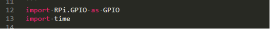
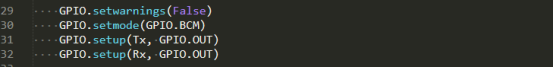
Import libraries used to control GPIO and time-related libraries.
Define the GPIO pin number related to RGB ultrasonic wave.

Call this function to get distance information.

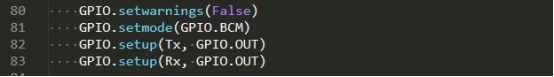
Initialize the GPIO pins. Because the GPIO pins have different functions when ultrasonic ranging and controlling the color of RGB lights, you need to initialize them according to specific functions before using related functions.
Control RGB ultrasonic wave to enter the ranging mode.

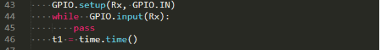
After detecting that the level of the Rx pin becomes low, it indicates that the ultrasonic wave has been sent out, and the time t1 is obtained.
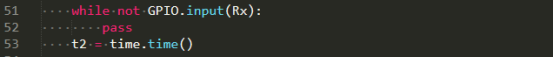
Detect the duration of the low level of the Rx pin, and obtain the time t2 when the Rx pin becomes high.
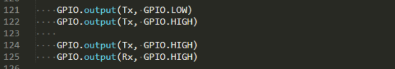
Control the RGB ultrasonic module to exit the ranging mode.

According to t1 and t2 and the speed of sound in the air, calculate the distance and return the value.

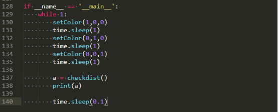
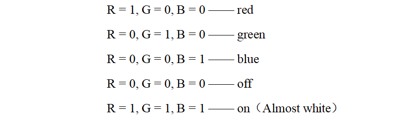
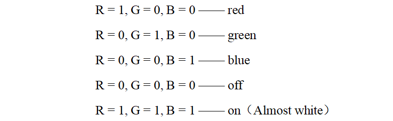
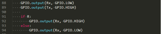
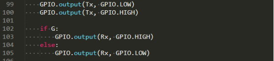
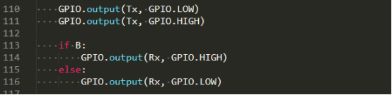
Call this function to change the color of the light on the RGB ultrasonic wave module, which is divided into three channels of red, green and blue. Each channel has two states (0 and 1). The following is about the color phenomenon that occurs when RGB is set to different values.

Initialize GPIO pins.
Enter the mode of changing color for the first time to set the R channel state.
Enter the color changing mode for the second time to set the G channel state.
Enter the mode of changing the color for the third time to set the state of the B channel.
Exit the mode of changing colors.
In the setColor() function, you can directly modify the 1 or 0 data of the parameter here to control the RGB ultrasonic sensor to light up different colors.