Links to resources about Alter Classic Car :
project address:https://github.com/adeept/alter
RobotGit:https://github.com/adeept/alter.git
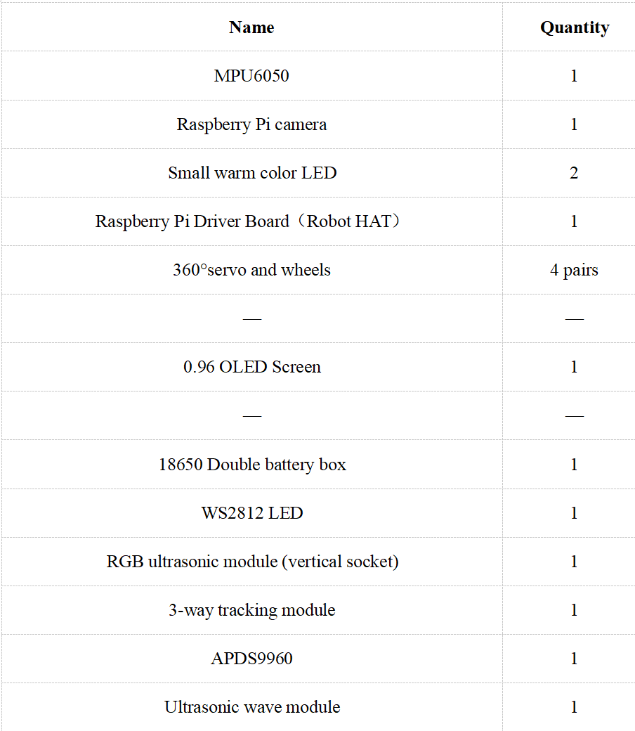
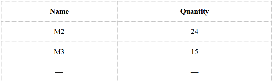
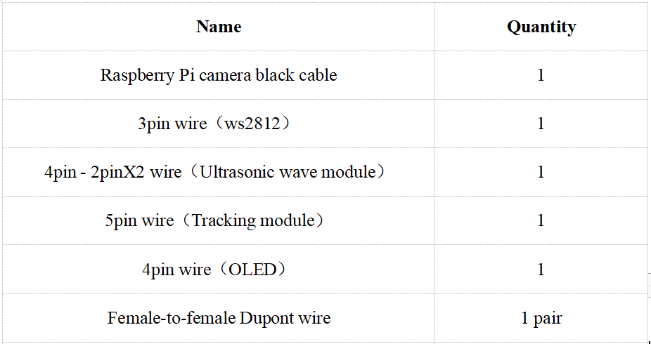
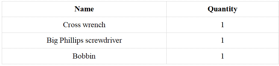
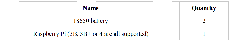
22.1 Parts list
Electrical parts:
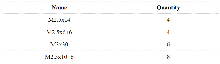
Copper pillar:
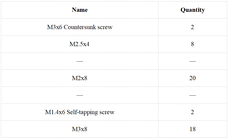
Screw:
Nut:
Wire:
Tool:
Own parts:
Screw color description:

In order to make the structural assembly process more intuitive, we dye the screws used in the product. During the assembly process, you can refer to the color of the fasteners in the tutorial to determine which type of screws and nuts to use.
The actual color of the product is subject to the product, and the actual screws are not colored.
Among them, the screws of M1.4x6 and M3x25 are very different, so we use silver in the tutorial without dyeing.
Name of aluminum alloy parts:
22.2 Wiring method
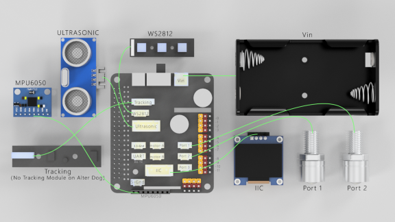
1. If you don't know how to connect the camera, you can refer to the official documentation of the Raspberry Pi camera.
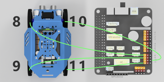
2. In the forward direction of Alter Classic Car, the front left servo is connected to PWM-8, the left rear servo is connected to PWM-9, the right front servo is connected to PWM-10, and the right rear servo is connected to PWM-11.
3. The ultrasonic module is connected to the Ultrasonic port with a 4pin cable. Never connect the ultrasonic module to the IIC port, which will cause permanent damage to the ultrasonic module.
4. The WS2812 light bar is connected to the WS2812 port using a 3pin wire. It should be noted that the signal to control the light is sent by the Raspberry Pi and sent to the WS2812 light bar with the 3PIN wire by the driver board. It needs to be connected from the light bar with a white stripe (the interface text on the back of this end is marked with IN).
5. The OLED screen is connected to the IIC port of the driver board with a 4PIN wire.
6. MPU6050 is inserted into the 8PIN DuPont port on the front of the driver board.
7. Connect the power supply to the VIN port.
8. The tracking module is connected to the Tracking port with a 5PIN wire. (Alter Dog does not install the tracking module)
22.3 Alter Classic Car Assembly Guide
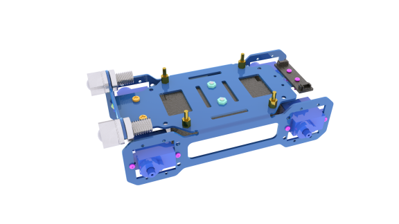
Use M2x8 screws and M2 nuts to install the blue 360°servo to A02.
Use M3x6 countersunk screws and M3 nuts to install the battery box to A02.
Use M3x8 screws and M3 copper pillars to install the tracking module to A02 (the white arrow on the tracking module faces the forward direction of the robot).
Use M2.5x4 screws to install M2.5x6+6 copper pillars to A02.
Use M2x8 screws and M2 nuts to install the WS2812 to A02.
like this:
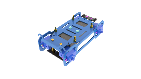
Install the small warm light LED to A02.
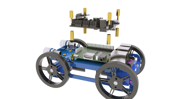
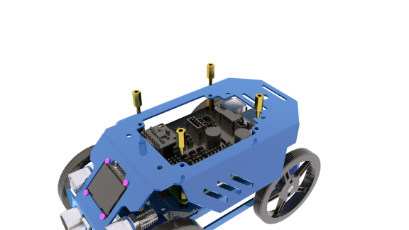
Use M2.5x14 copper pillars to install the Raspberry Pi to A02.(If the Raspberry Pi cannot be installed or the holes are not aligned, the reason is that the structure of the A02 is bent. You need to remove the battery box, and then use both hands to restore the bent and deformed A02 until it can be adjusted to fit the Raspberry Pi driver board.)
Use M2.5x10+6 copper pillars to install Robot HAT driver board to Raspberry Pi.
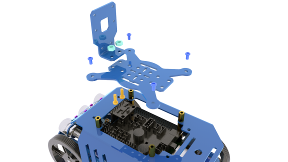
Use M1.4x6 tapping screws to install the blue ultrasonic module to A01.
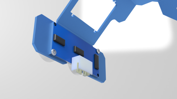
Use M2x8 screws and M2 nuts to install the OLED screen to A01.
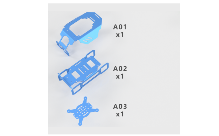
Use M2.5x10+6 copper pillars to install A01 to A02.
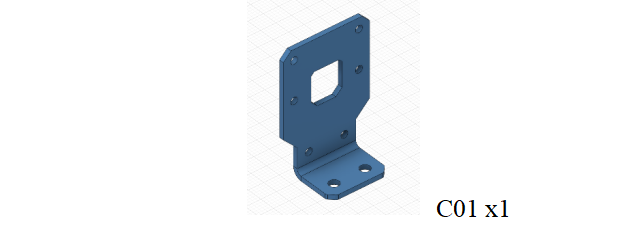
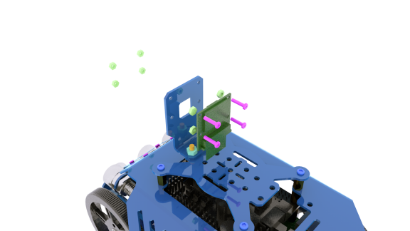
Install C01 to A03 by using M3x8 screws and M3 nuts.
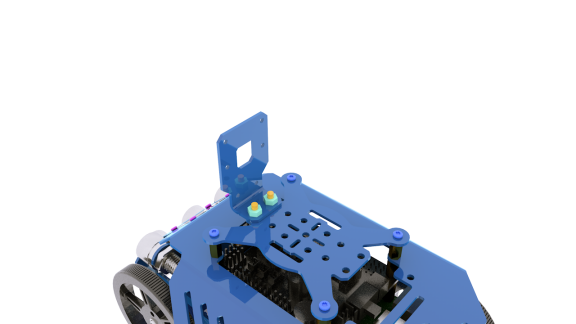
Use M2.5x4 screws to install A03 to A01.
Use M2x8 screws and M2 nuts to install the camera module to C01.
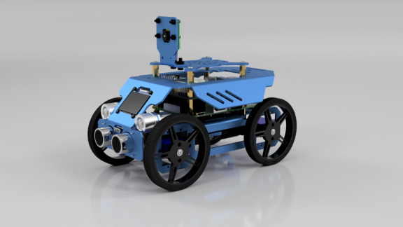
The assembly is complete.
22.4 Tips for Structural Assemblage
Since many servos are used in the product, the servo installation is critical for the robot. Before installing the rocker arm to the servo, you need to connect the servo to power and make the servo shaft rotate to the central position, so the rocker arm installed at the designated degree will be in the central position.
Generally Raspberry Pi will auto run `webServer.py` when booting, when `webServer.py` will control all the ports connected to servos to send a signal of rotating to the central position. When assembling the servo, you can connect it to any servo port anytime. After connecting the servo to the port, the gears will rotate to the central position; assemble the rocker arm to the servo, disconnect the servo from the port, and insert more servos to repeat rocker arm assembly (all servos will be in the central position).
When the servo is connected to power, try moving the rocker arm. If it can't be moved, it indicates the program for the servo works; otherwise there's error for the servo program. Run the line `[RobotName]/initPosServos.py` (replace `[RobotName]` with the folder name of your robot's program) to make the servo rotate to the central position.
When booting (it may take 30-50s), it takes a while for the Raspberry Pi to control PCA9685 to set signal of all servo ports for central position rotating.
22.5 Tips for Power Provision
When you install the software, assemble the structure and debug the program, you can use a USB cable to power the raspberry pi. If the raspberry pi is installed with Motor HAT, you can connect the USB cable to the USB interface on the Motor HAT. Motor HAT will supply power to the raspberry pi through the GPIO interface.
The demand of different raspberry pi for electric current is different. For example, the raspberry pi 3B needs at least 2A of current to start up, and the raspberry pi 4 needs 3A to start up normally. You can check the specifications on your power adapter before you use the power adapter to power the raspberry pi.
When Motor HAT is connected to a load (such as connecting to a motor or multiple servos), you need to use a power supply that supports high current to connect to Vin on Motor HAT. You can use two 18650 batteries that support high current to power Motor HAT. Our product will provide a dual 18650 battery box with 2pin interface, you can directly connect it to Motor HAT.
When you use the USB interface on Motor HAT to supply power, Motor HAT's switch does not control whether to supply power, Motor HAT's switch can only control the power supply of Vin.
Do not use the USB interface and Vin on the Motor HAT to supply power at the same time. If you need to debug the program for a long time and do not want to remove the battery, you can set the switch on the Motor HAT to OFF. So, when using a USB cable to connect Motor HAT, Motor HAT is powered by USB.
If your robot restarts automatically after starting up or the robot disconnects and restarts suddenly when it starts moving after been started up normally, it is most likely because your power supply does not output enough current. When the robot is starting up, it will automatically run the program to put all the servos in the neutral position. The voltage drop caused by this process causes the raspberry pi to restart.
We have tested that when using 7.4V power supply, the peak current of the robot is about 3.75A, so you need to use a battery that supports 4A output.
You can also use a power lithium battery to power Motor HAT. Motor HAT supports the power supply that is below 15V.
You can use a USB cable to supply power to Motor HAT when the installing the rocker arm of the servo during structural assembly. After the robot software is installed, the raspberry pi will control Motor HAT to set all servo ports to output the neutral signal after it is started up. At this time, you can connect the servo to any servo port, the servo gear will turn to the neutral position, and then you can install the rocker arm of the servo according to the specified angle. After the rocker arm is installed, the servo can be disconnected from Motor HAT. When you need to install the rocker arm of the second servo, you only need to connect the second servo to any servo port on the drive board.