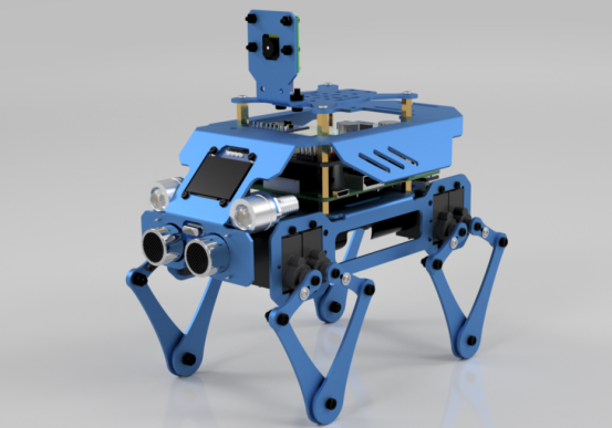
In this lesson, we will learn the mathematical principle of inverse kinematics of the Alter Dog's servo. You need to prepare the installed Alter Dog robot.
30.1 Mathematics Principles of Inverse Kinematics of the Servo Link
Robot kinematics includes forward kinematics and inverse kinematics. Forward kinematics is to calculate the position and posture of the end of the robot given the joint variables of the robot; Inverse kinematics is to know the position and posture of the end of the robot and calculate all the corresponding positions of the robot joint variables. Generally, the solution of forward kinematics is unique and easy to obtain, while inverse kinematics often has multiple solutions and the analysis is more complicated. Robot inverse motion analysis is an important problem in motion planning and uncontrollable. However, due to the complexity and diversity of the robot inverse motion problem, it is impossible to establish a general analytical algorithm. The inverse kinematics problem is actually a problem of solving nonlinear transcendental equations, including a series of complex problems such as the existence, uniqueness and solving method of the solution. Inverse kinematics is the process of determining the parameters of the joint movable object to be set to achieve the required posture. For example, given a three-dimensional model of the human body, how to set the angle of the wrist and elbow so that the hand changes from a relaxed position to a waving gesture? This problem is very critical in robotics, because manipulating robotic arms is controlled by joint angles.
The mathematical principle of inverse kinematics of the servo connecting rod of the Alter Dog robot is as follows:
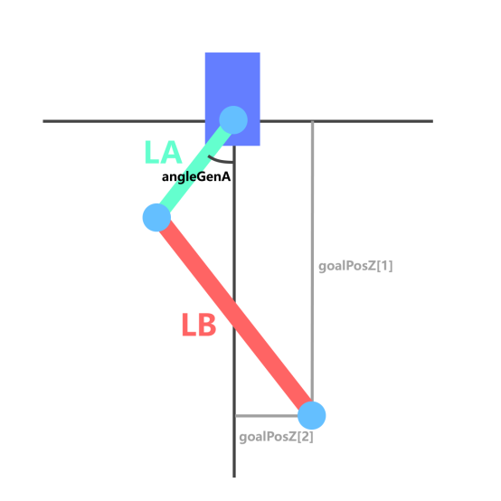
As shown in Figure A below, according to the coordinates of the end points of the legs (goalPosZ[1] and goalPosZ[2]) and the length of each joint, the value of angleGenA can be calculated by using trigonometric functions.
But only using this value does not limit the end point. The end point can still rotate around the articulation point of the link between LA and LB, so an extra set of links must be added.
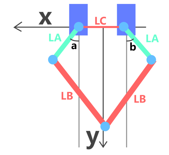
From Figure B and Figure A below, we can find the values of ∠a and ∠b by adding extra LC parameters, and since the end point of the connecting rod has a unique solution, the landing position of the robot leg can be controlled by changing the values of ∠a and ∠b.
30.2 Learning the code program of this lesson
Here we use Subline IDE to view and edit the code program of this lesson, please see the content of lesson 2 for specific methods. The specific code and comments are as follows:
In the file manager of the MobaXterm terminal, find the directory:
adeept_alter/server
And open the code of this lesson: linkageMATH.py.
Import the library used to control the servo.

Import math function library.

Instantiate the library used to control the servo.

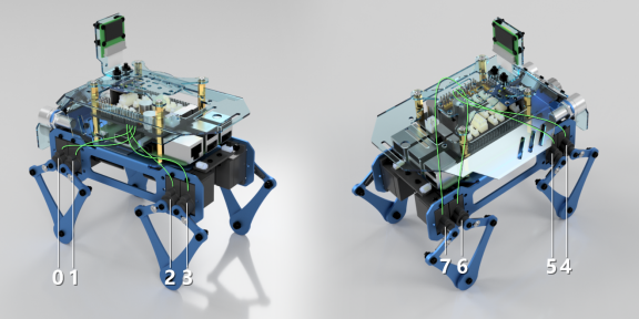
When the rocker arm of the servo is vertically downward, the corresponding PWM value of the servo; here only the forward left leg of the DOG is taken as an example; the corresponding PWM port numbers of the two servos on the left front leg are 0 and 1 respectively; the specific values of the two variables here are different for each robot.

This array is used to adjust the swing direction of each servo.

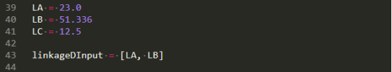
LA is the length of the first joint of the connecting rod, LB is the length of the second joint of the connecting rod, and LC is the distance between the two servo axes in a leg.
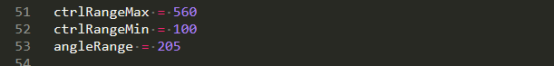
Parameters related to servo angle control: ctrlRangeMax is the maximum effective PWM of the servo; ctrlRangeMin is the smallest effective PWM of the servo; angleRange is the actual rotation range of the servo.
This function enters the angle to return the PWM value.

This function passes in the length parameters of the two connecting rods of the leg, the servo number and the coordinate point, and the return value is the angle that the servo needs to swing.

Here the mathematical principles can refer to Figure A in the first half of this course.
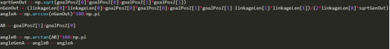
By multiplying the returned angle by sc_direction[servoNum].

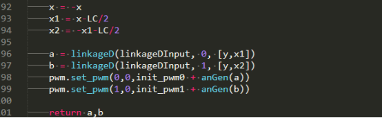
This function passes in the coordinate point and controls the movement of the point at the end of the leg to the coordinate point, and returns the angle of the two servos at the same time.

Here the mathematical principles can refer to Figure B in the first half of this course.
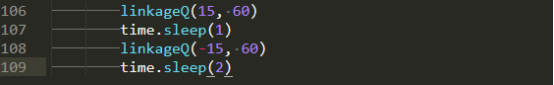
Control the servo to turn 15° in the forward direction for 1s; then turn it in the reverse direction for 15° for 2s.
30.3 Run the program of this course
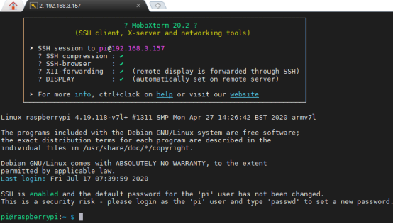
1. Open the terminal software MobaXterm:

2. Log in to your Raspberry Pi (the way to log in to Raspberry Pi has been introduced in Lesson 1):
3. Enter the Course Code folder, this folder stores the sample code program to control the robot, enter the following command:
cd adeept_alter/server

4. Enter the command to display the contents of the current directory:
ls
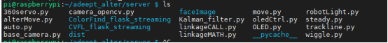
5. linkageMATH.py is the sample code for this lesson, enter the command to run this program:
sudo python3 linkageMATH.py

6.After successfully running the program, you can observe the movement of the robot's legs.