Assembly tutorial
Preparations before Assembly
|
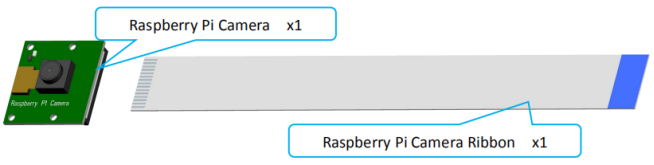
1. Connect the Raspberry Pi Camera and the ribbon. Assemble the following components.
|
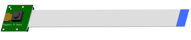
Effect diagram after assembling.
|
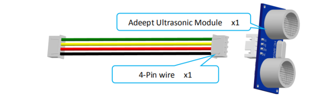
2. Connect the Adeept Ultrasonic Module with 4-Pin wire. Assemble the following components.
|
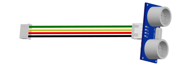
Effect diagram after assembling.
|
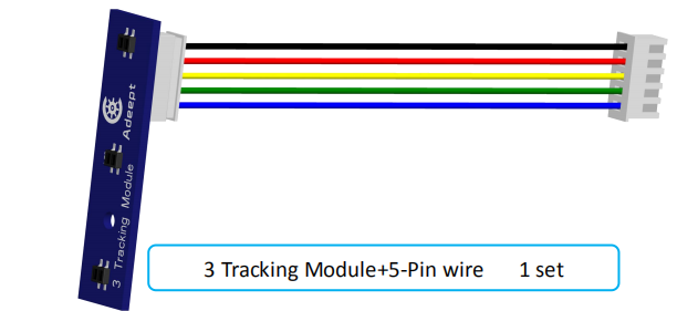
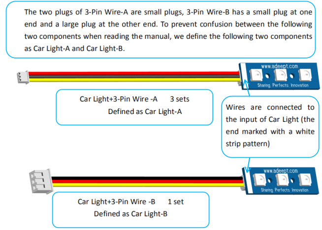
The connection diagrams of the remaining modules and wires are as follows.
|
|
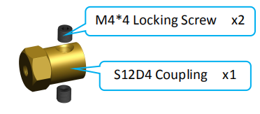
3. Screw the M4*4 Locking Screw into the S12D4 Coupling (2 sets). Assemble the following components
|
Assemble the Raspberry Pi
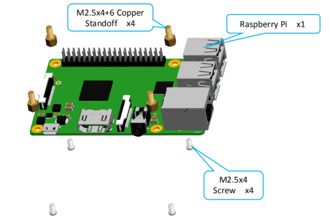
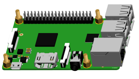
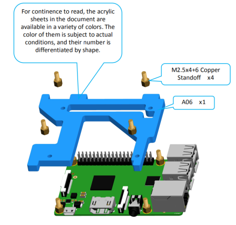
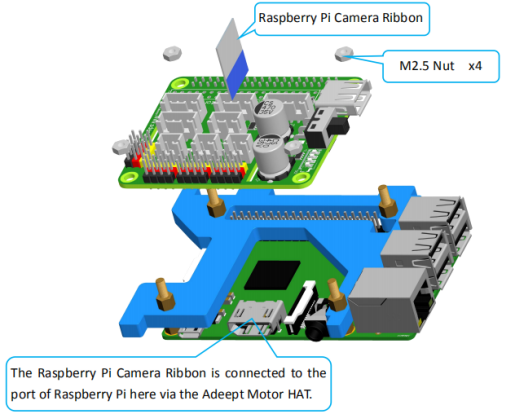
1. Fix four M2.5x4+6 Copper Standoffs on Raspberry Pi. Assemble the following components.(The Raspberry Pi is not included in the kit.)
|
Effect diagram after assembling.
|
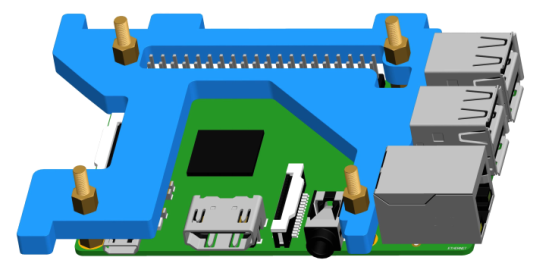
2. Fix A06 to Raspberry Pi. Assemble the following components.
|
Effect diagram after assembling.
|
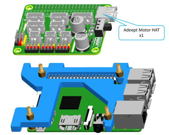
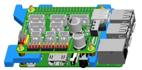
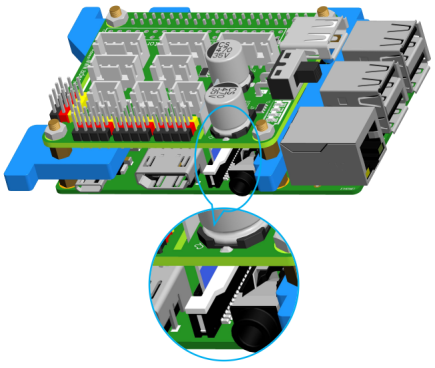
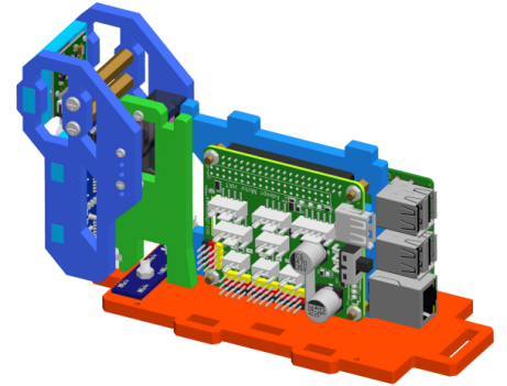
3. Insert the Adeept Motor HAT into Raspberry Pi. Note: You need to install the camera cable to the Raspberry Pi.(Not shown in the picture) Assemble the following components.
|
Effect diagram after assembling.
|
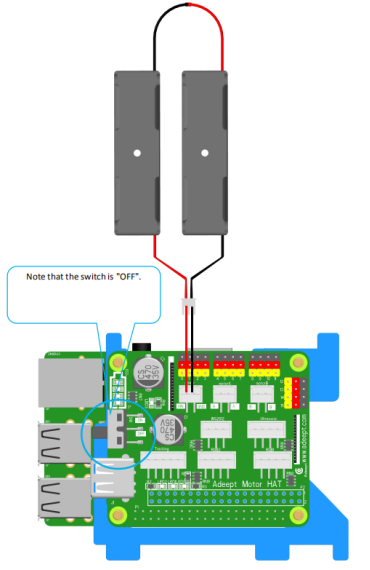
If you have adjusted the servo to the middle position, the next steps can be ignored. 4. Connect the 18650 Battery Holder Set to the Adeept Motor HAT.
|
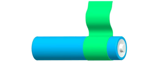
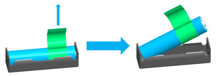
5. Put two 18650 batteries in 18650 Battery Holder Set according to the following method. Take out 1 ribbons and 1 batteries.
|
Roll one end of the ribbon to let through a battery and fix.
|
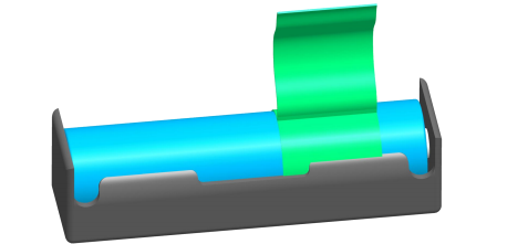
Insert the batteries into the rings - ribbon closer to the anode.
|
Install the batteries into the holder based on the pole.
|
To remove the batteries, just pull the ribbon and take them out.
|
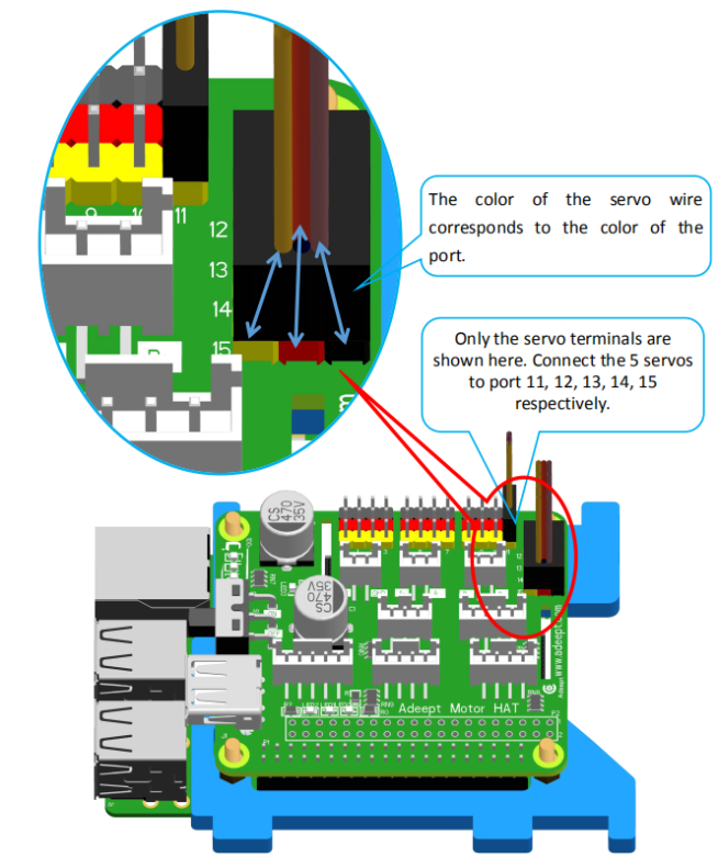
6. Connect five servos to Adeept Motor HAT.
|
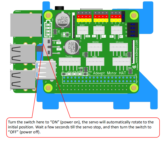
7. Turn on the power and debug the servo. Before switching on, you need to insert the configured SD card into the Raspberry Pi. For details, please refer to the third chapter of the document. That in the next operation, the Pi Camera of the Raspberry Pi should always be connected to the Raspberry Pi, and do not reverse the wires of the Raspberry Pi. Otherwise, the servo will not rotate to the middle position after booting. If SD card is not inserted, the servo needs to be rotated to the middle position manually.
After debugging, remove the servo and battery holder, and take the 18650 batteries out of the Holder Set. Do not rotate the rotation axis before the servo fixed to the rocker arm. Otherwise, you need to re-debug the servo. |


Rocker arm assembly
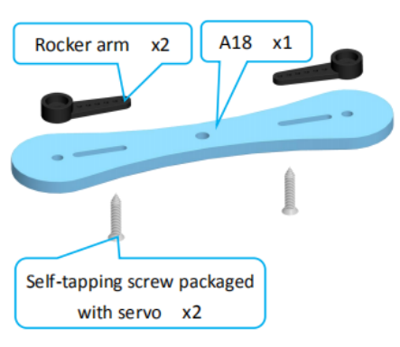
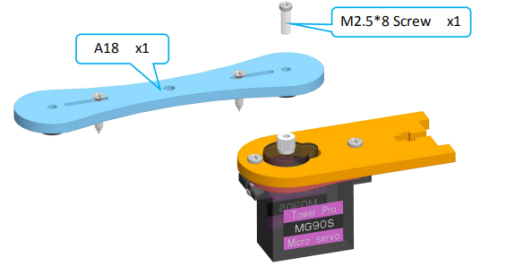
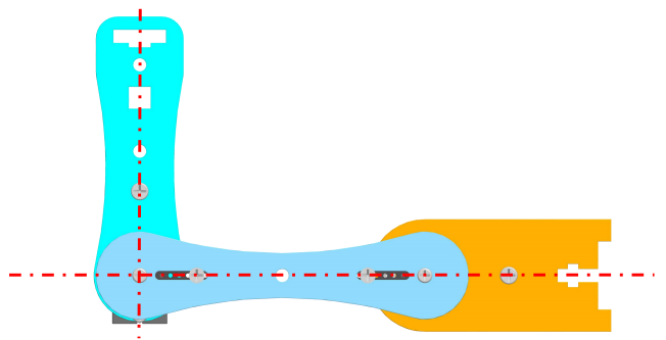
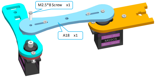
1. Take two rocker arms as in the illustration and connect them to A18. Assemble the following components.
|
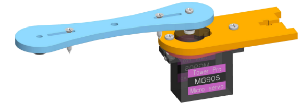
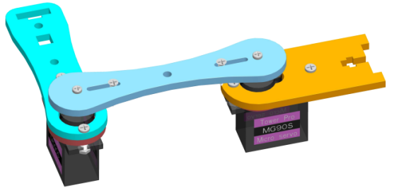
Effect diagram after assembling.
|
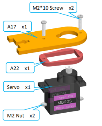
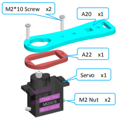
2. Fix a debugged servo to A17. Assemble the following components.
|
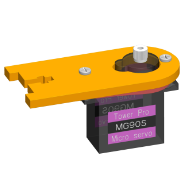
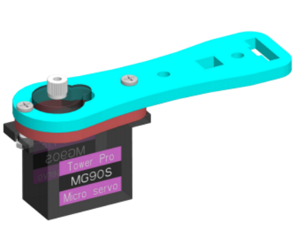
Effect diagram after assembling.
|
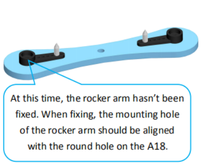
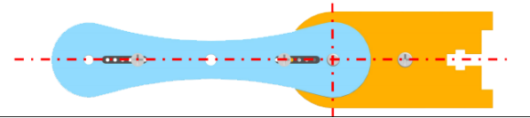
3. Then fix one end of A18 to the servo on A17. First install the rocker arm on the A18 into the servo. When installing, the mounting hole of the rocker arm should be aligned with the round hole on the A18. Install it at the angle shown below.
|
Assemble the following components When fixing the acrylic and the servo, you need to install the rocker arm to the servo first, and then fix it with screws.
|
Effect diagram after assembling
|
4. Fix a debugged servo to A20. Assemble the following components
|
Effect diagram after assembling
|
5. Then fix the other end of the A18 to the servo on the A20. First install the rocker arm on the A18 into the servo. When installing, the mounting hole of the rocker arm should be aligned with the round hole on the A18. Install it at the angle shown below.
|
Assemble the following components
|
Effect diagram after assembling
|
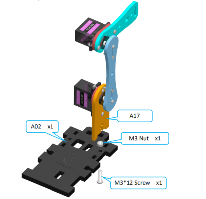
6. Then fix A17 to A02. Assemble the following components
|
Effect diagram after assembling
|
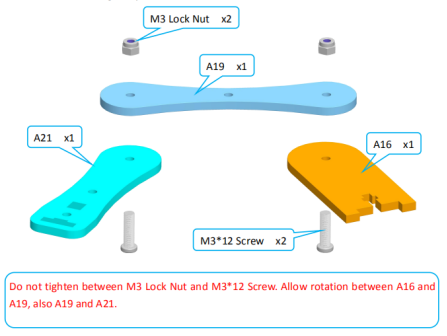
7. Connect A16 with A19 and A21. Assemble the following components
|
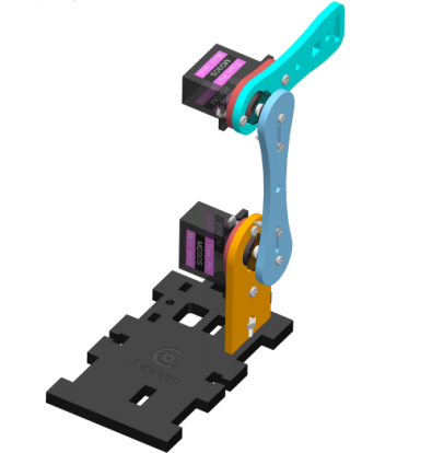
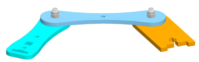
Effect diagram after assembling
|
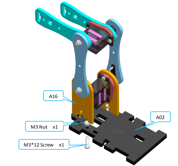
8. Fix A16 to A02. Assemble the following components
|
Effect diagram after assembling
|
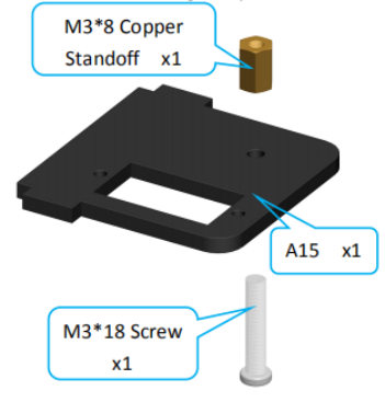
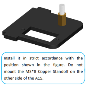
9. Fix one M3*8 Copper Standoff to A24. Assemble the following components
|
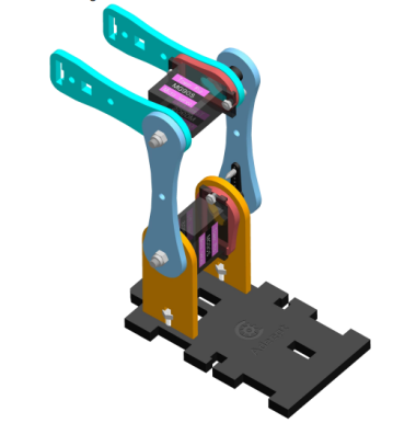
Effect diagram after assembling
|
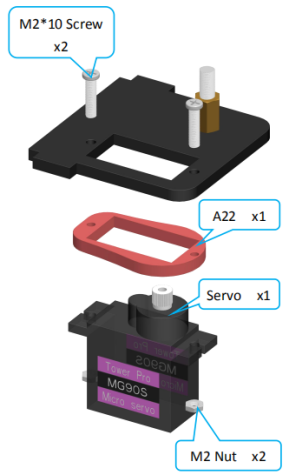
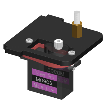
10. Fix a debugged servo to A24. Assemble the following components
|
Effect diagram after assembling
|
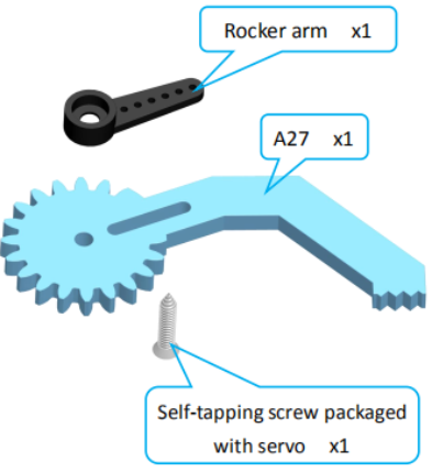
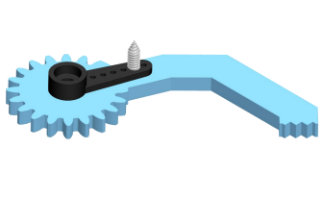
11. Fix one rocker arm of the servo to A27. Assemble the following components
|
Effect diagram after assembling
|
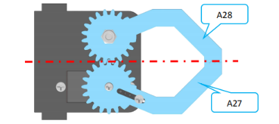
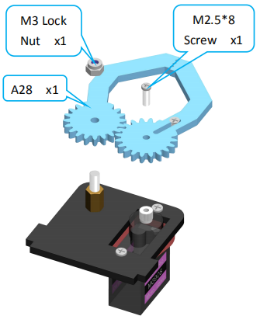
12. Assemble A27 and A28. Install A27 and A28 as shown below.
|
Assemble the following components
|
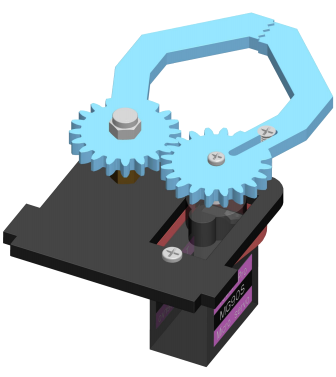
Effect diagram after assembling
|
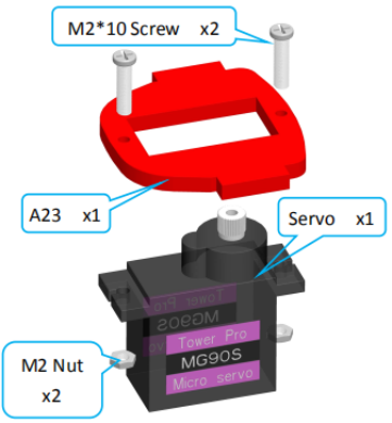
13. Fix a debugged servo to A23. Assemble the following components
|
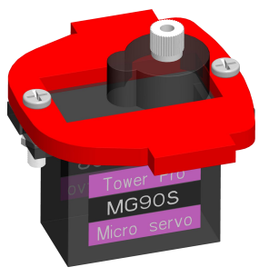
Effect diagram after assembling
|
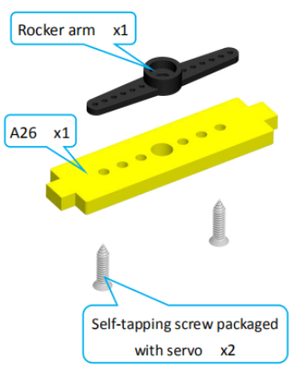
14. Fix a rocker arm to A26. Assemble the following components
|
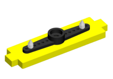
Effect diagram after assembling
|
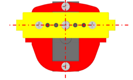
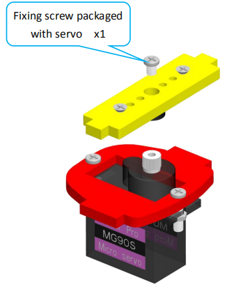
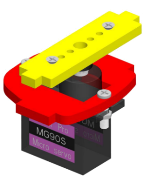
15. Fix the rocker arm on the A26 to the servo on the A23. Install as shown below.
|
Assemble the following components
|
Effect diagram after assembling
|
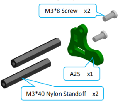
16. Fix one A25 with two M3*40 Nylon Standoffs. Assemble the following components
|
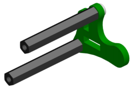
Effect diagram after assembling
|
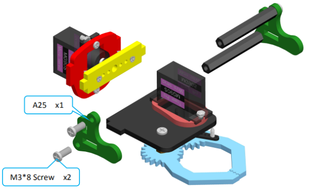
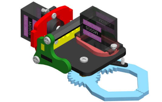
17. Complete assembly of the clamp section. Assemble the following components
|
Effect diagram after assembling
|
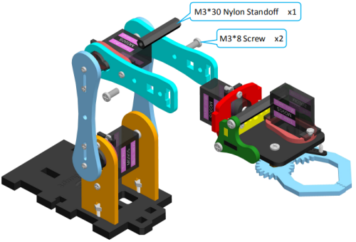
18. Install the clamp section on the robotic arm. Assemble the following components
|
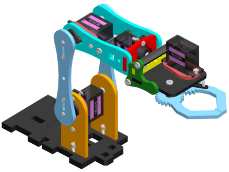
Effect diagram after assembling
|
Body part assembly
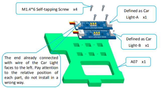
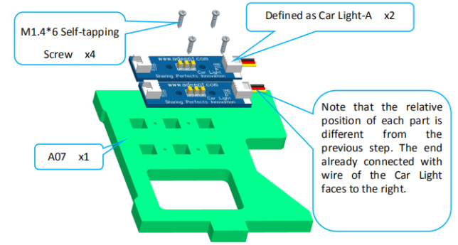
1. Fix two Car Lights on A07. Assemble the following components
|
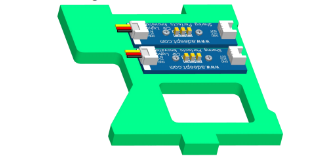
Effect diagram after assembling
|
| 2. Fix two Car Lights on the other A07. Assemble the following components
|
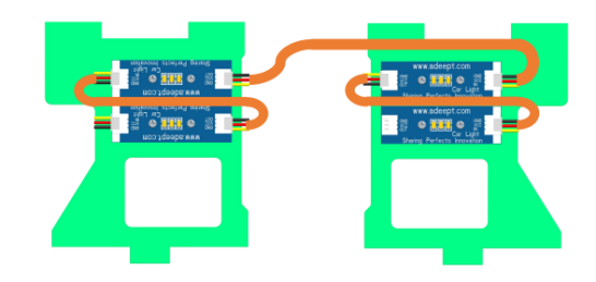
3. Connect the Car Light as shown below.
|
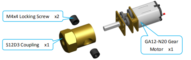
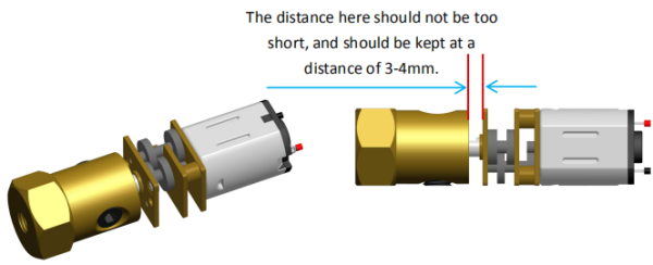
4. Fix S12D3 Coupling on GA12-N20 Gear Motor (2 sets). Assemble the following components
|
Effect diagram after assembling
|
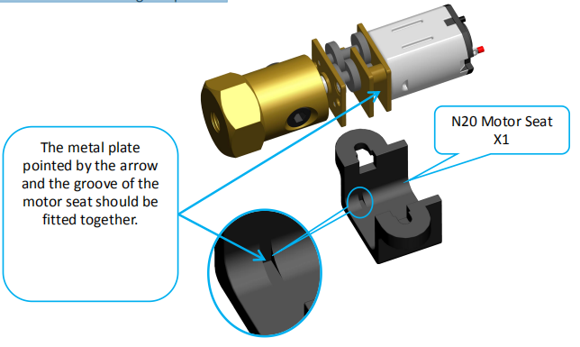
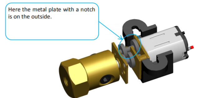
5. Put the GA12-N20 Gear Motor on N20 Motor Seat (2 sets). Assemble the following components Note: Please keep the motor installation position consistent with the picture, which will affect the smoothness of the tracked vehicle's rotation.
|
Effect diagram after assembling
|
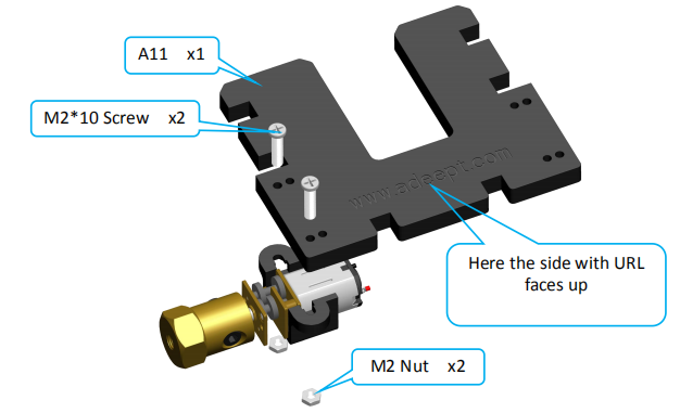
6. Fix N20 Motor Seat on A11. Assemble the following components
|
Effect diagram after assembling
|
Fix the other N20 Motor Seat on A11.
|
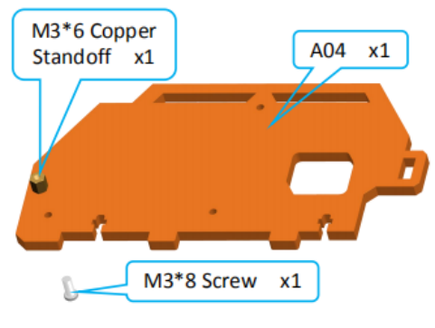
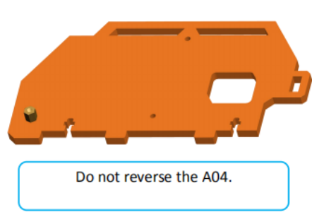
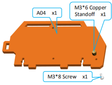
7. Fix one M3*6 Copper Standoff on A04. Assemble the following components
|
Effect diagram after assembling
|
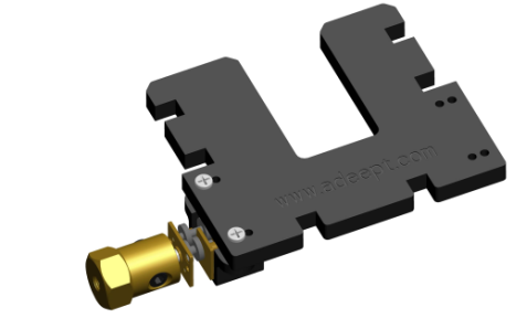
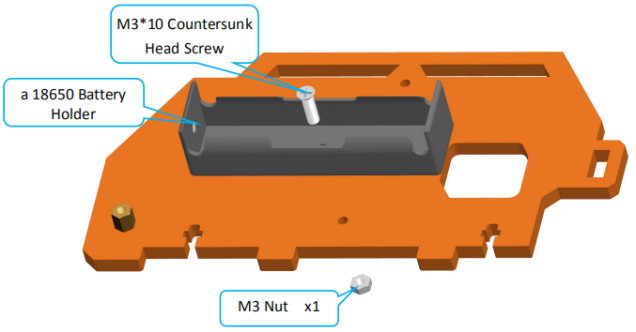
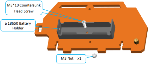
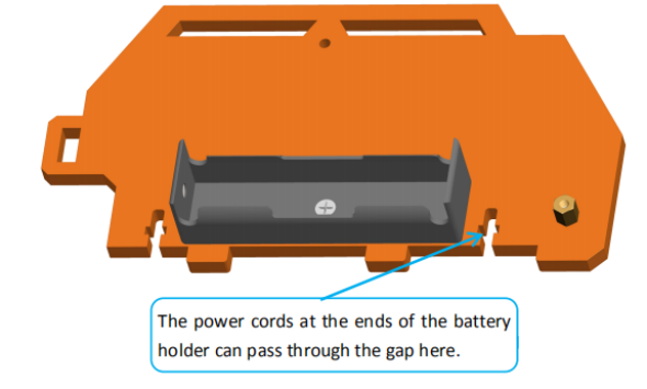
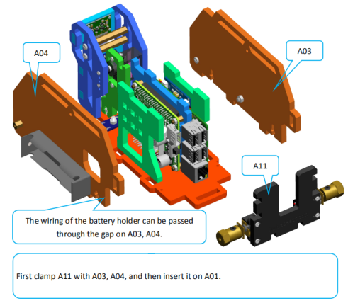
8. Fix one section of the 18650 Battery Holder Set to A04. Assemble the following components
|
Effect diagram after assembling
|
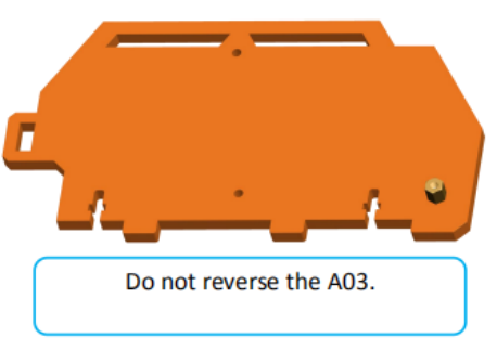
9. Fix one M3*6 Copper Standoff on A03. Assemble the following components
|
Effect diagram after assembling
|
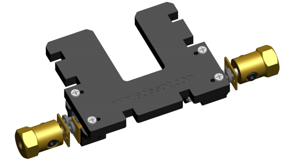
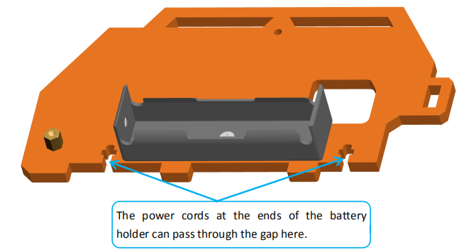
10. Fix the other section of the 18650 Battery Holder Set to A04. Assemble the following components
|
Effect diagram after assembling
|
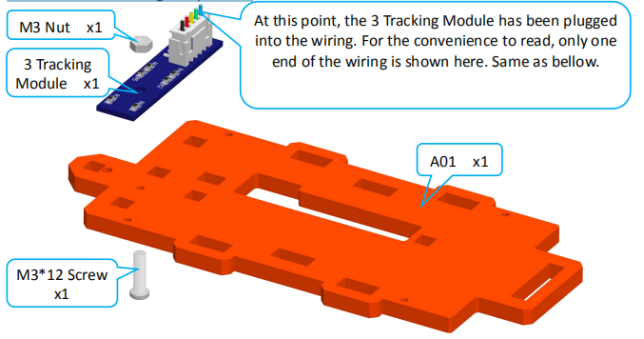
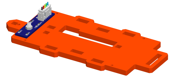
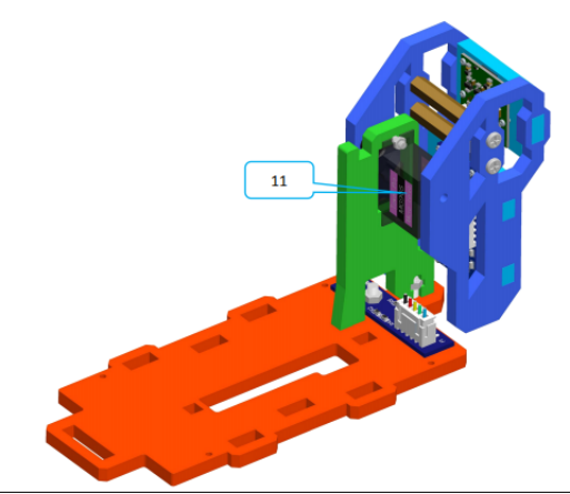
11. Fix 3 Tracking Module on A01. Assemble the following components
|
Effect diagram after assembling
|
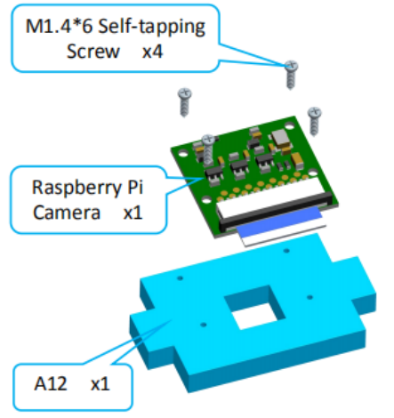
12. Fix Raspberry Pi Camera on A12. Assemble the following components
|
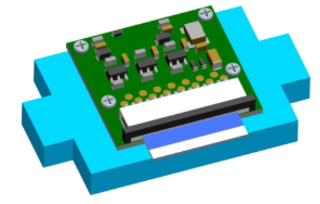
Effect diagram after assembling When the screw is obstructed or cannot be screwed in, turn over the plate and screw in the other side.
|
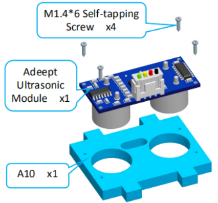
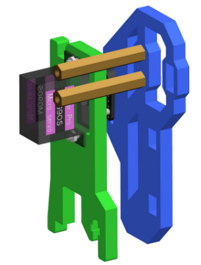
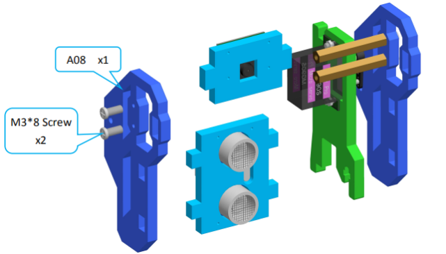
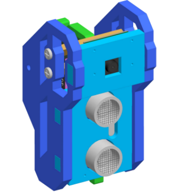
13. Fix Adeept Ultrasonic Module on A10. Assemble the following components
|
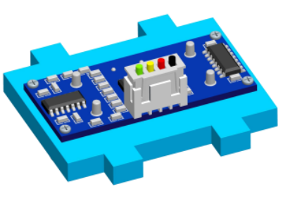
Effect diagram after assembling When the screw is obstructed or cannot be screwed in, turn over the plate and screw in the other side.
|
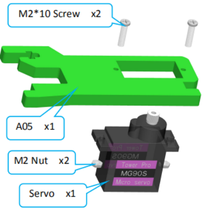
14. Fix a debugged servo to A05. Assemble the following components
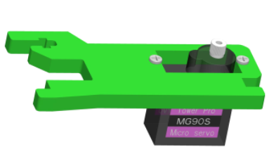
|
Effect diagram after assembling
|
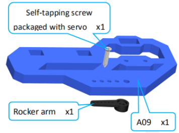
15. Fix one rocker arm of the servo on A09. Assemble the following components
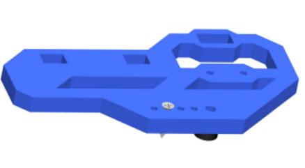
|
Effect diagram after assembling
|
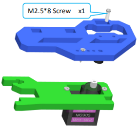
16. Fix the rocker arm on A09 to the servo on A05. Buckle the rocker arm into the servo at the angle shown in the figure below.
|
Assemble the following components The M2.5*8 screws here are used to fix the relative position of the steering gear, and do not need to bear a large force, just make sure that the acrylic and the steering gear will not fall off. When installing, first install the rocker arm on the rotation axis of the steering gear, and then install the M2.5*8 screws.
|
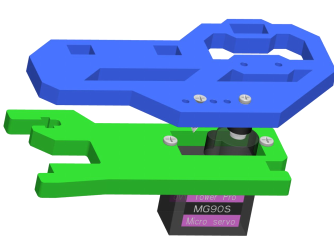
Effect diagram after assembling
|
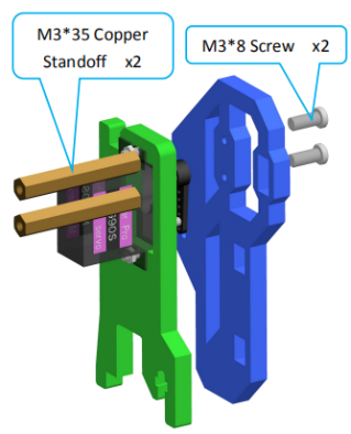
17. Fix two M3*35 Copper Standoffs on A09. Assemble the following components
|
Effect diagram after assembling
|
18. Fix A10 and A12 between A08 and A09. Assemble the following components
|
Effect diagram after assembling
|
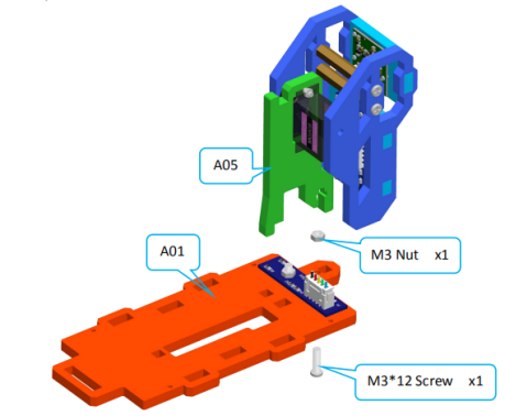
19. Fix A05 on A01. Assemble the following components
|
Effect diagram after assembling
|
20. Connect the other end of Raspberry Pi Camera Ribbon with Raspberry Pi. Assemble the following components
|
Effect diagram after assembling
|
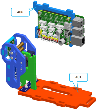
21. Insert A06 to A01. Assemble the following components
|
Effect diagram after assembling
|
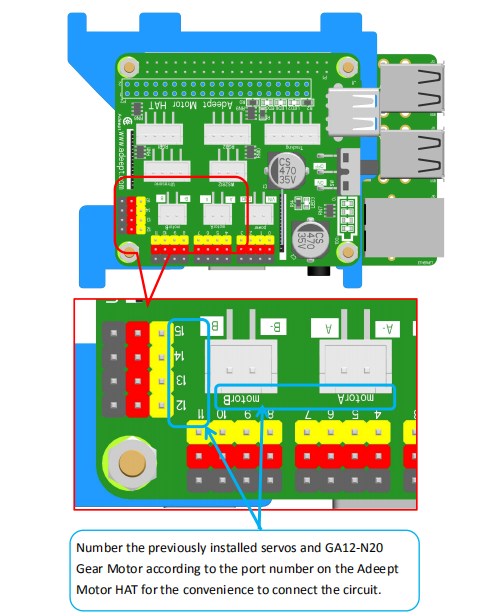
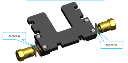
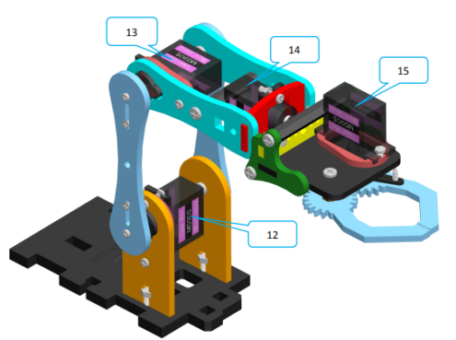
22. Connect the circuit. Connect the servo with GA12-N20 Gear Motor. Note: The servo(15) at the farthest distance on the robotic arm needs to use a servo extension cable to extend the servo cable.
|
|
|
|
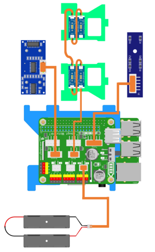
Connect the servo and the GA12-N20 Gear Motor to the corresponding port numbers of Adeept Motor HAT. Connect the Adeept Ultrasonic Module, Car Light, 3 Tracking Module and 18650 Battery Holder Set as shown below. Note: Confirm that the interface of the battery box is correctly connected.
|
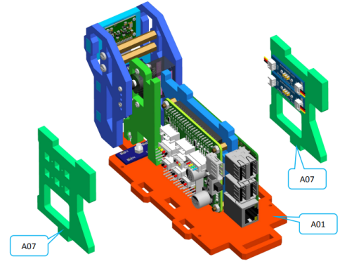
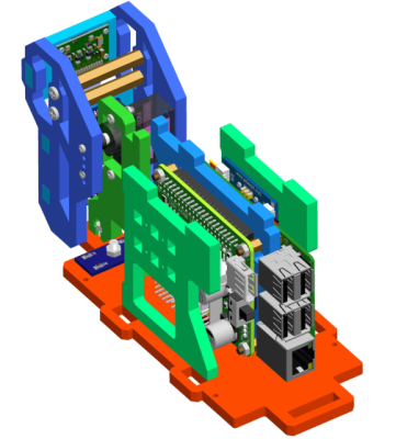
23. Insert A07 to A01. Assemble the following components
|
Effect diagram after assembling
|
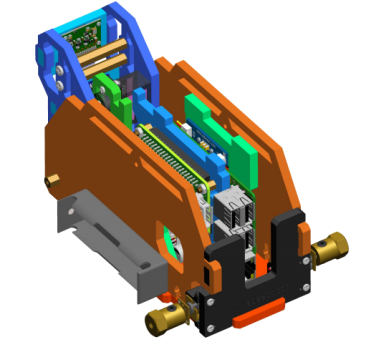
24. Insert A03, A04 and A11 on A01. Assemble the following components
|
Effect diagram after assembling
|
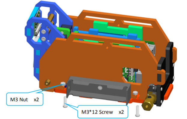
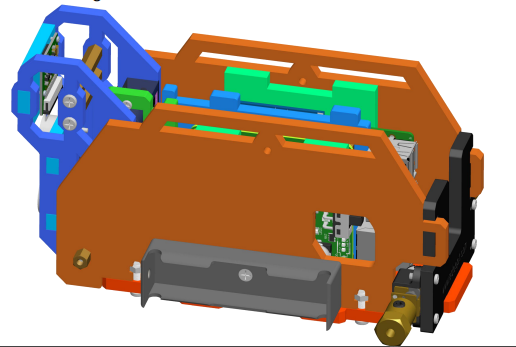
25. Fix A04 with M3*12 Screw. Assemble the following components
|
Effect diagram after assembling
|
Fix A03 with M3*12 Screw.
|
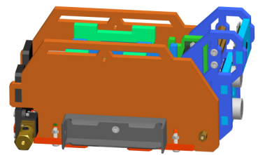
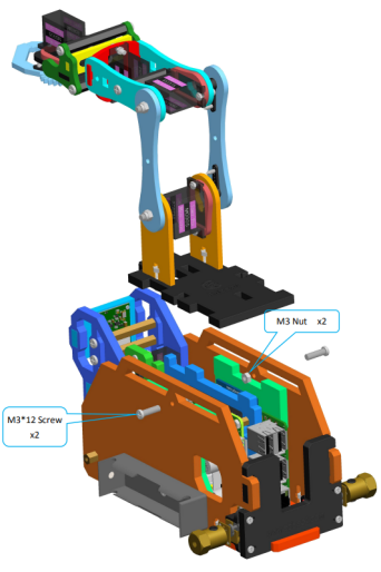
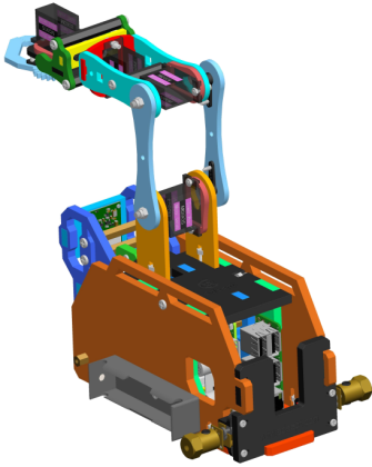
26. Fix A02 to A03 and A04. Assemble the following components
|
Effect diagram after assembling
|
Track assembly
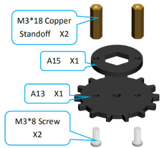
1. Fix A13 to A15 (4 sets). Assemble the following components
|
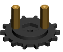
Effect diagram after assembling
|
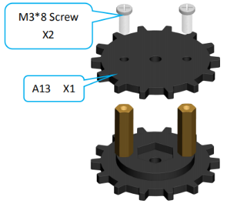
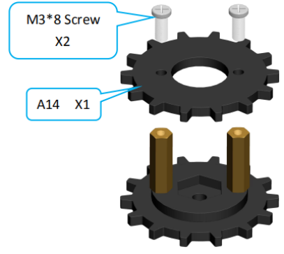
2. Assemble driving wheel (2 sets). Assemble the following components
|
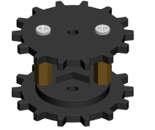
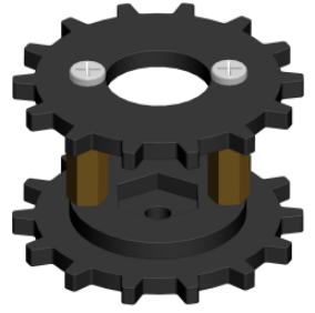
Effect diagram after assembling
|
Assemble driven wheel (2 sets). Assemble the following components
|
Effect diagram after assembling
|
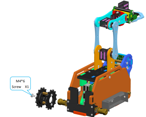
4. Install the driving wheel on the S12D4 Coupling. Assemble the following components
|
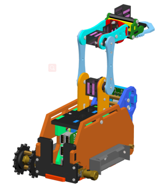
Effect diagram after assembling
|
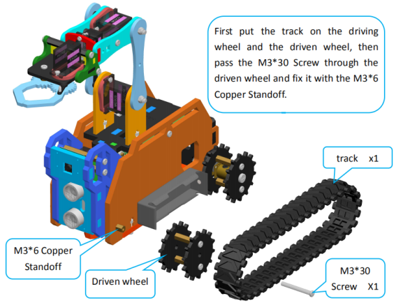
5. Install the left track of the tank. Assemble the following components Before installing the driven wheel, you need to fix the track on the two wheels first, otherwise the track will not be installed. After fixing the driven wheel, try to rotate the crawler to see if it can rotate smoothly. If it cannot rotate smoothly, this is caused by the fact that the two wheels are not in the same horizontal plane. You need to adjust the driving wheel/driven wheel to make the crawler rotate smoothly.
|
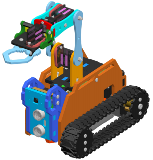
Effect diagram after assembling
|
|