In this lesson, we will carry out an interesting experiment by programming on the Micro:bit so as to read Potentiometer data.
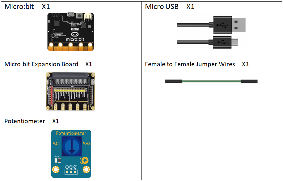
23.1 Components to be prepared
23.2 The introduction of Potentiometer
23.2.1 Potentiometer
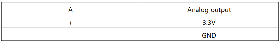
The potentiometer is actually a variable resistor with three lead-out segments. The potentiometer is usually composed of a resistor body and a movable brush. When the brush moves along the resistor body, a resistance value or voltage that has a certain relationship with the displacement amount is obtained at the output end.
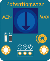
The potentiometer module used in this experiment.
23.3 Low level and high level
In circuit, the form of binary (0 and 1) is presented as low level and high level.
Low level is generally equal to ground voltage (0V). High level is generally equal to the operating voltage of components.
The low level of Micro:bit is 0V and high level is 3.3V, as shown below. When IO port on Micro:bit outputs high level, low-power components can be directly driven,like LED.

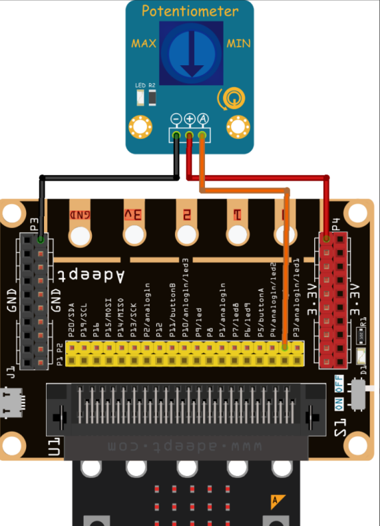
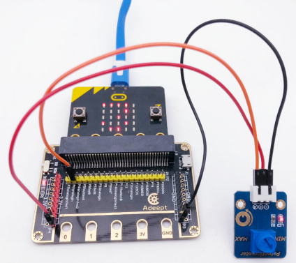
23.4 Circuit
You need to connect the components according to the circuit diagram below.
23.5 MakeCode programming
Next, we will use the online MakeCode Editor to complete the experiment in this lesson.
23.5.1 Start programming
(1) Log in to the website
1. You need to enter the URL in the address bar of Google Browser:
https://makecode.microbit.org/
2. After the website is successfully opened, the interface as shown below will appear:

(2) Import a project
1. In the HOME interface, click the "Import" button to import the external ".hex" file:

In the pop-up dialog box, select the "Import File", as shown in the following figure:

Click the "Choose File"

Find the code file for this lesson:
BBC_Microbit_Sensor\Code\Lesson_23\BlockCode
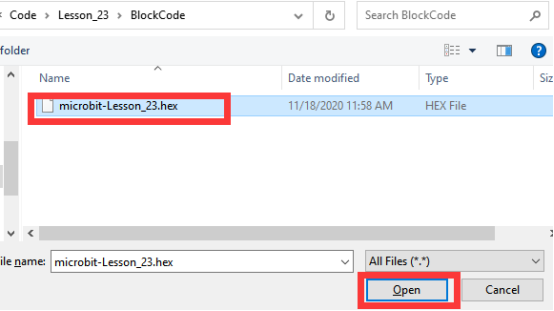
Select the file in ".hex" format and click the Open:
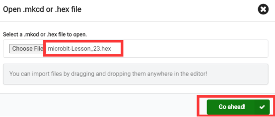
2. Notice whether the file has been loaded into the following window, and then click the "Go ahead!" button, as shown in the following figure:
3.You can see the following interface when successfully opening the file:
23.5.2 Run the program
1. After the program is written, connect micro:bit and PC with a Micro USB cable.
2. After micro:bit is connected to the computer, you need to first "Pair device". Click the  button on the right of
  in the lower left corner, and then click the
  option, as shown in the following figure:

Then click  in the lower right corner

Then the following dialog box will pop up, select  , and then click

After the device is successfully paired, the  button changes to

3. Start to download the program to Micro:bit, and click the  button. Generally, the program will be downloaded directly to the Micro:bit. After the download is completed, your Micro:bit will restart and run the program just downloaded. Watch the LED screen of Micro:bit, and you will see the Potentiometer data, as shown below:

[Note]
If no experimental phenomenon has been detected after clicking the button  , you need to click the
  button on the right of the
  , and then click the
  , and observe the Micro:bit again, as shown in the following figure:

If you have problems, please send us an email: support@adeept.com
23.5.3 Learn the code program
The following instruction blocks will be applied in the program. Please see the description of the function as follows:
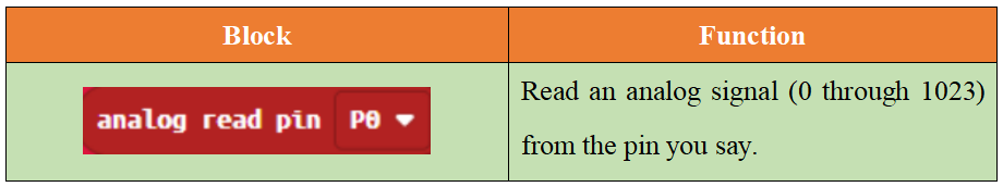
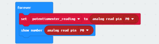
Read the analog quantity of potentiomer with the instruction block  , and finally output the data to LED screen of Micro:bit.

23.6 Python programming
23.6.1 Run the program
1.Connect micro:bit and PC with a Micro USB cable.
2. Open the Mu Editor installed on the computer, and click the button [Load] in the upper left corner to open the source code program of this lesson:

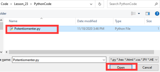
Find the code file for this lesson:
BBC_Microbit_Sensor\Code\Lesson_23\PythonCode
Select the file in ".py" format and click the Open:
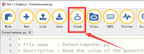
3. Click the [Flash] button to download the program to Micro:bit, as shown in the following figure:
4.After successfully downloading the program, watch the LED screen of Micro:bit, and you will see the Potentiometer data, as shown below.
If you have problems, please send us an email: support@adeept.com
23.6.2 Learn the code program
Read the illumination data of the potentiometer with the read_analog(); finally output the data to LED screen of Micro:bit.
12 13 14 15 16 | while True: # define potentiometer pin potentiometer_reading = pin0.read_analog() display.scroll(str(potentiometer_reading)) sleep(1000) |