Assembly tutorial
Robotic arm assembly
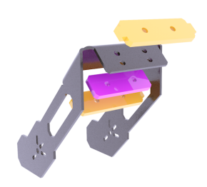
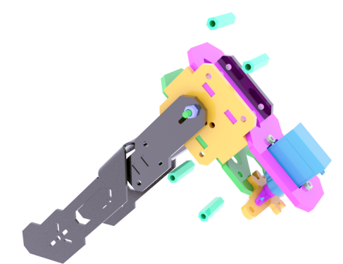
Prepare the following structure.
|
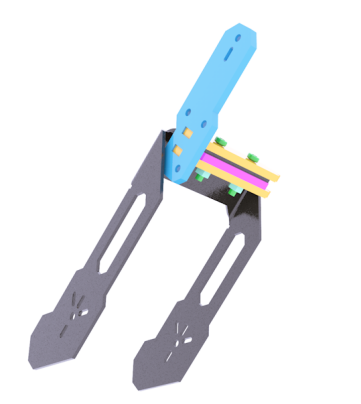
Use two M3X16 screws and two M3 nuts to fix the three acrylic panels shown above on the aluminum alloy base of the robotic arm.
|
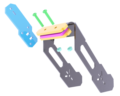
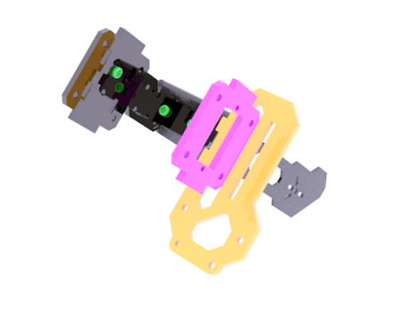
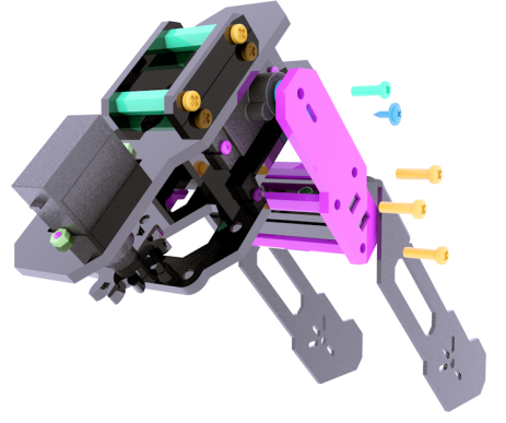
Prepare the acrylic panel shown on the right side of the above picture. There is no need to fix it on the assembled component. Since the acrylic panel on the right has directions, the rendering diagram will fix it on the component to indicate the subsequent assembly position.
|
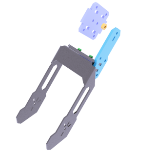
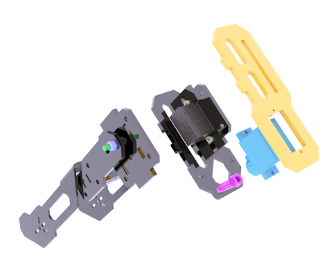
Prepare the acrylic panel and acrylic gasket as shown in the picture above.
|
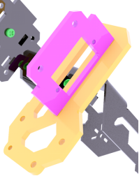
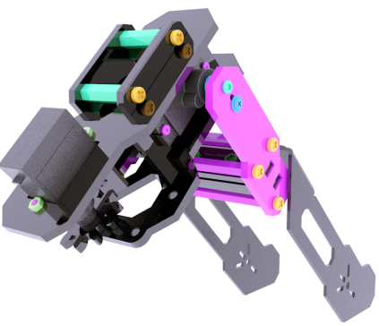
Use M3X16 screws and M3-LOCK lock nuts to fix the acrylic panel and acrylic washer as shown in the figure on the side panel. It should be noted that the lock nut should not be tightened too tightly, because this is the rotating pair of the movable part. After tightening, it will not be able to rotate and the servo will be blocked. Note: All lock nuts involved in this document should not be tightened. A Cross Socket Wrench is required for screwing self-locking nuts.
|
|
|
|
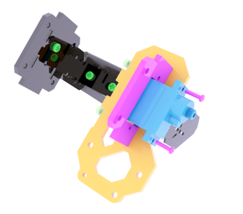
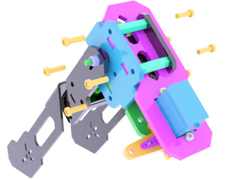
Use M2X8 screws and M2 nuts to fix the AD002 servo on the acrylic panel shown in the figure above. The acrylic panel here is similar in shape to the acrylic panel just installed, except that there are more mounting holes for fixing the servo.
|
|
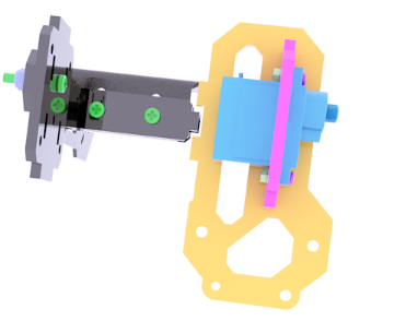
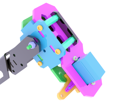
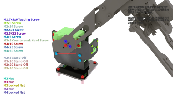
It looks like the picture above after installation. Prepare the acrylic panel (top panel of GRIPPER) and AD002 servo as shown in the picture. Use M2X8 screws and M2 nuts to fix AD002 servo to the upper panel of the arm chuck.
|
|
|
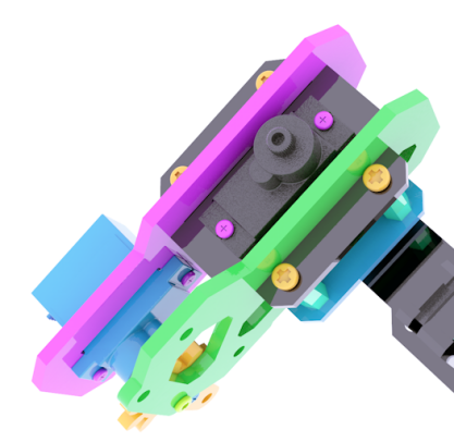
Assemble the upper panel and lower panel of the chuck. Here you can load the gear shown above between the servo arm and the lower panel. For the time being, you don’t need to fix it. You only need to know that the gear is installed here. The gear is clamped in this position to avoid the gear cannot be installed due to too small gap after assembly.
|
Use M2.5*12 screws and M1.7*6*6 self-tapping screws to fix.
|
|
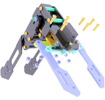
Use four M3X20 nylon posts and eight M3X10 screws to fix the left and right panels of the chuck together.
|
|
|
|
|
|
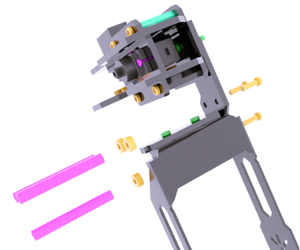
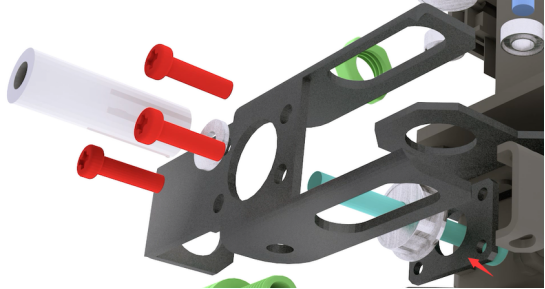
Use three M3X10 screws to fix the acrylic washer and M3X40 nylon column to the side panel of the robot arm.
|
|
|
Use three M3X10 screws to fix the panel on the other side. Use M1.7X6X6 self-tapping screws to fix the side panel and the servo arm, and use M2.5X8 screws to fix the servo to the side panel.
|
|
|
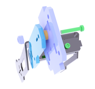
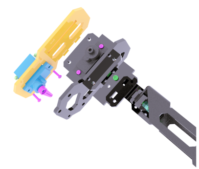
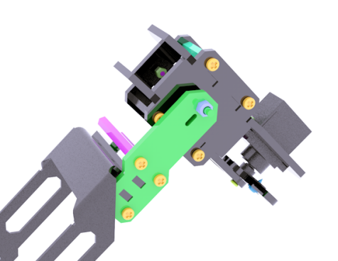
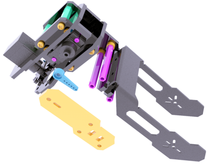
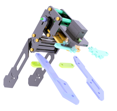
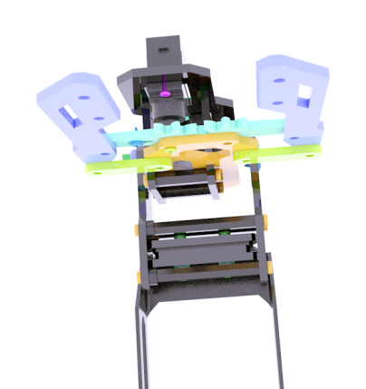
The assembled look is shown in the figure above. Prepare the gear on the other side and the connecting rod parts for the chuck.
|
|
|
|
|
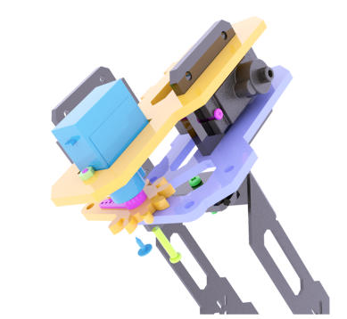
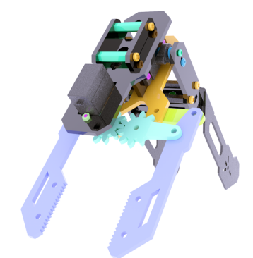
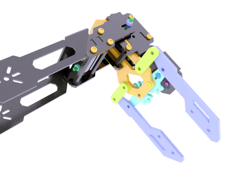
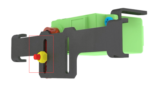
The installation method is shown in the figure above. Use M3X10 screws and M3-LOCK locknuts to assemble the connecting rods.
|
|
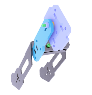
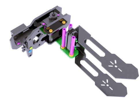
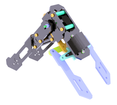
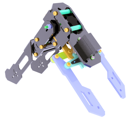
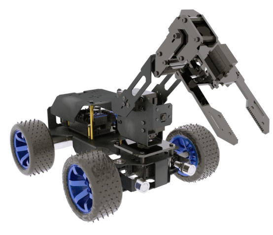
The robot arm after assembly is as shown in the figure above. |
PTZ installation
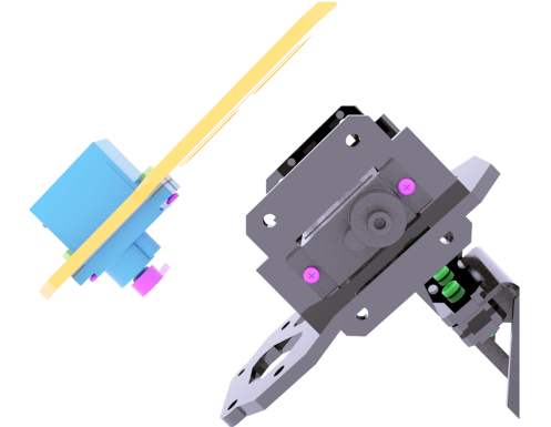
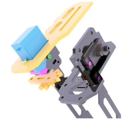
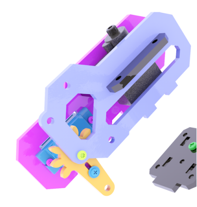
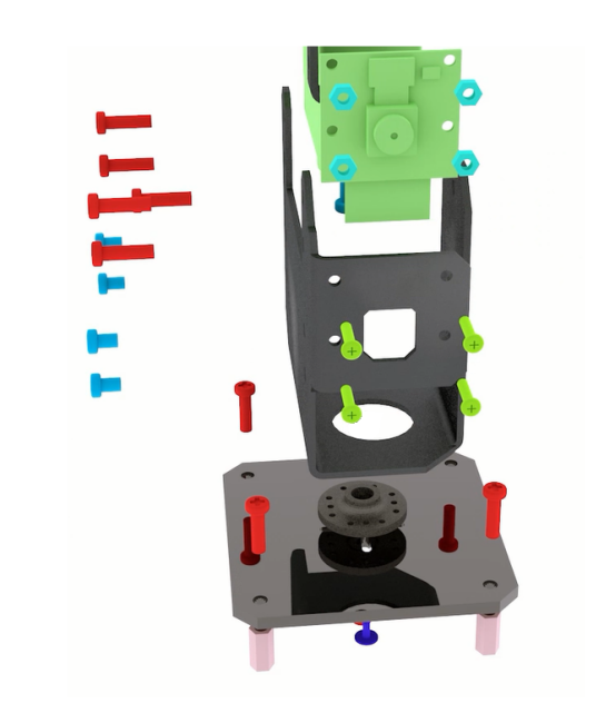
Prepare 2 large servos, a camera, and the following parts.
|
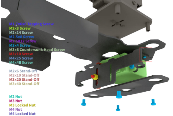
Use 8 M2 nuts on the front and back sides of the camera mounting hole, use M2*8 screws to pass through the aluminum alloy and the camera and fix them with M2 nuts. Use 4 M1.7*6*6 screws to pass through the acrylic base plate to fix the steering wheel, and then use one M3*10 screw to pass through the acrylic base plate --- steering wheel --- Servo from the bottom.
|
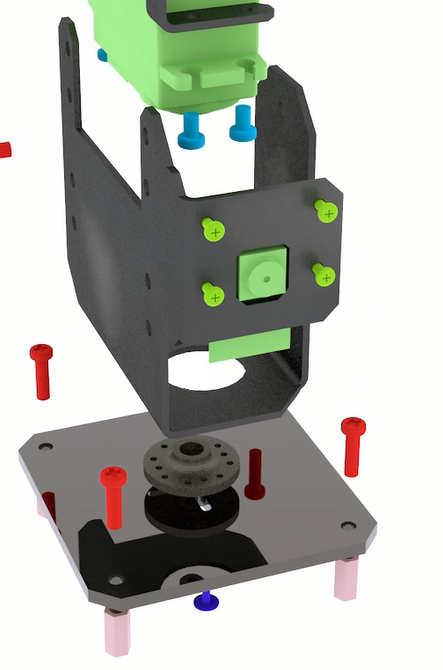
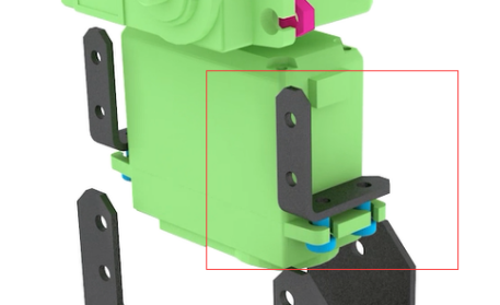
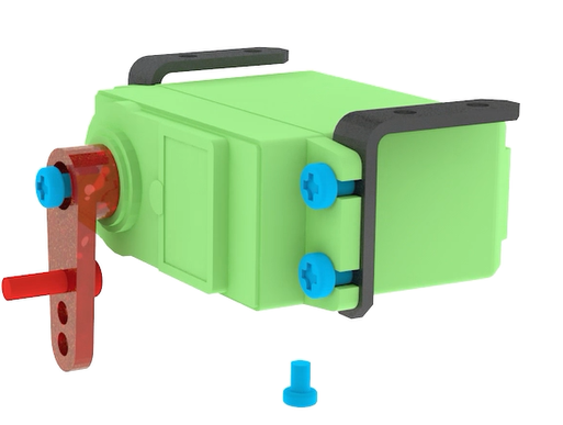
Use M3*4 screws to fix two "L"-shaped aluminum alloys.
|
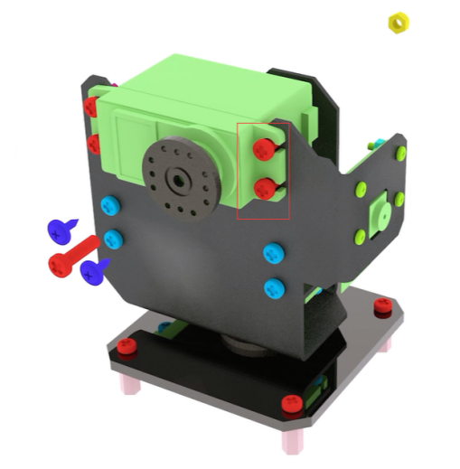
Use M3*4 screws to pass through the aluminum alloy and "L" aluminum alloy to fix the servo.
|
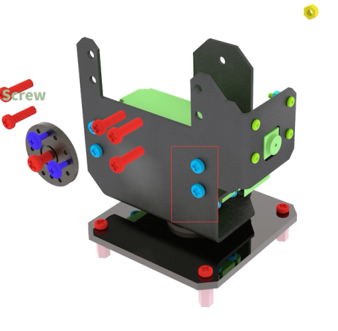
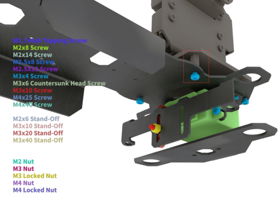
Install an M3*10 screw, no need to fix, for the connection of the PTZ and the robot arm.
|
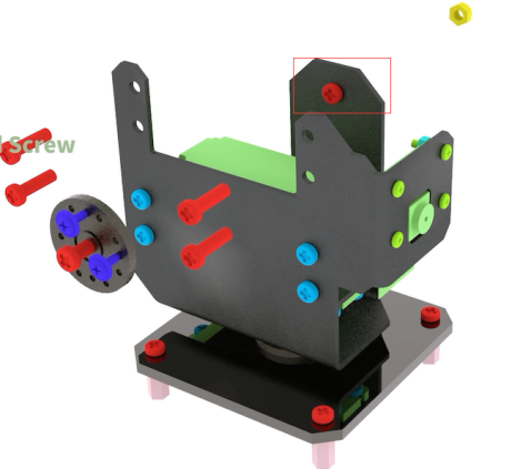
Use M3*10 screws to pass through the aluminum alloy and the servo and fix them with M3 nuts. Install the steering wheel.
|
Body installation
Use M3*4 screws to fix the "L" type aluminum alloy on the servo, install the rocker arm, fix it with M3*4 screws, and use M3*10 screws to pass through the rocker arm. (Due to the issue of the production version of the servo, if the M3*4 screw cannot fix the rocker arm, please use the M3*10 screw to fix it) |
|
Install the aluminum alloy and fix it with M3 lock nuts (all lock nuts in this course do not need to be tightened).
|
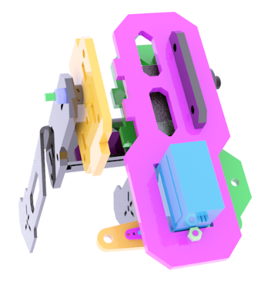
Prepare the aluminum alloy as shown below.
|
Install the aluminum alloy pictured above. Use 4 M3*4 screws to pass through the aluminum alloy and the "L" aluminum alloy on the servo to fix the servo.
|
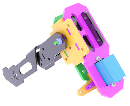
Install the PTZ. Use M3*4 screws to pass through the aluminum alloy and fix with M3*15 nylon posts.
|
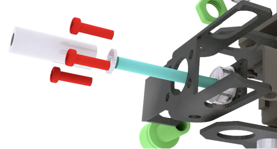
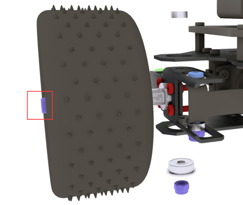
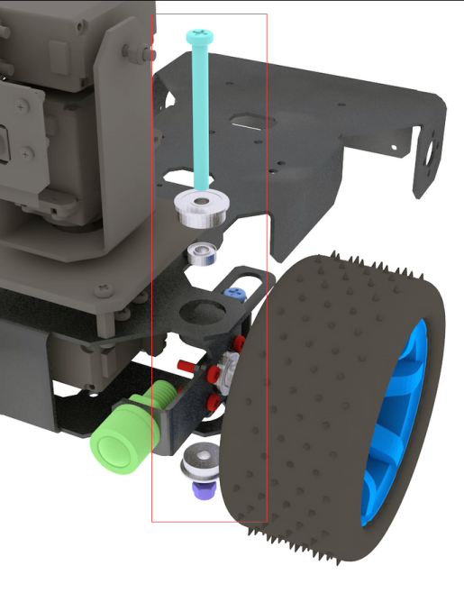
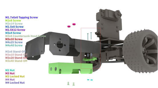
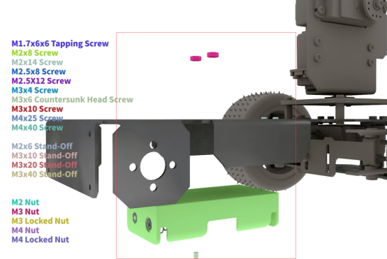
Prepare the aluminum alloy sheet (as shown by the arrow in the figure below), M4*40 screws, F624ZZ bearing (large), aluminum alloy, M4*8*1 gasket, plastic tube, and M4 nut.
|
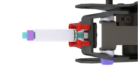
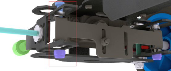
Use M4*40 screws to pass through the aluminum alloy sheet, F624ZZ bearing, aluminum alloy, gasket, plastic tube, and M4 nut from the inside to the outside. As shown below.
|
|
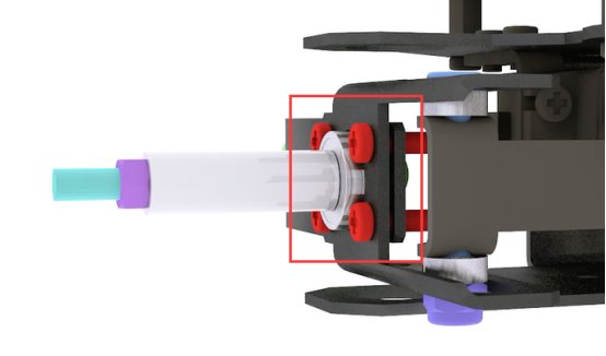
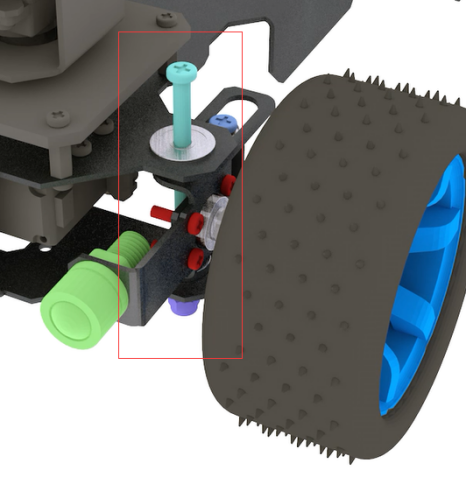
Use M3*10 screws to fix aluminum alloy and aluminum alloy sheet.
|
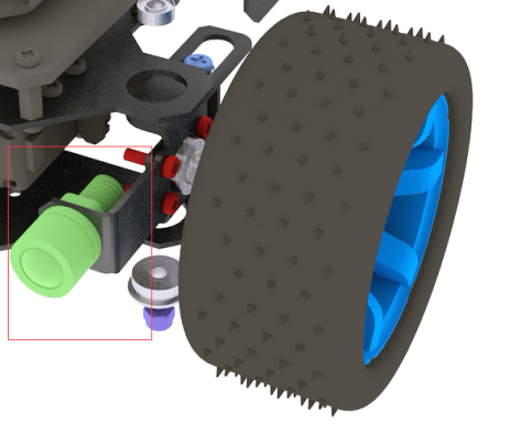
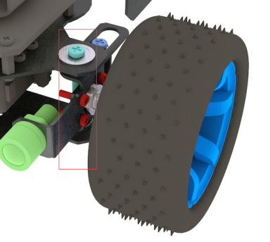
Install the tire and fix it with M4 locknut.
|
Install small LED lights.
|
Repeat the above steps to assemble the structure on the other side.
|
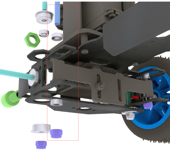
Use M4*40 screws to pass through these from top to bottom: MF84ZZ bearing (small), aluminum alloy (long large hole), aluminum alloy (small hole), aluminum alloy (small hole), aluminum alloy (long large hole) , MF84ZZ bearing (small), M4 nut. As shown below.
|
|
Use M4*40 screws to pass through these from top to bottom: F624ZZ bearing (large), MF84ZZ bearing (small), aluminum alloy (large hole), aluminum alloy (small hole), aluminum alloy (small hole), aluminum alloy (large hole), F624ZZ bearing (large), M4 nut. As shown below.
|
|
|
Install WS2812 LED lights. Use M2*14 screws to pass through the aluminum alloy, M2*6 copper column, ws2812 LED lights and fix them with M2 nuts.
|
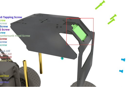
Install the battery holder. Use M3*6 countersunk screws to pass through the battery holder, aluminum alloy and fix them with M3 nuts.
|
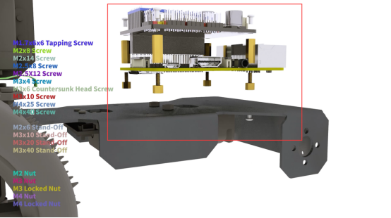
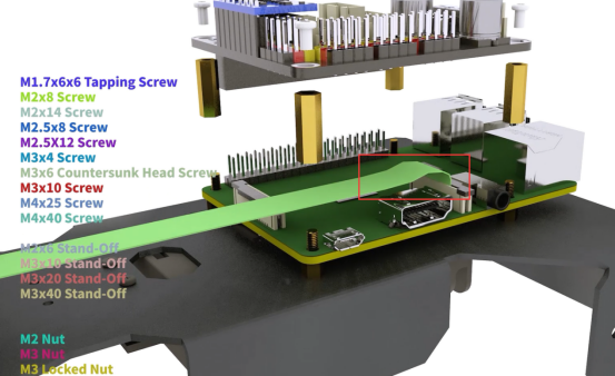
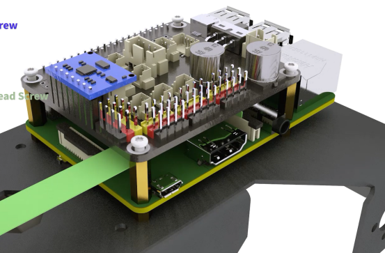
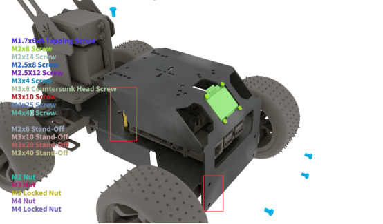
Install the Raspberry Pi and Robot HAT driver board. Use M2.5*4 screws to penetrate the bottom of the aluminum alloy and fix them with M2.5*4+6 copper pillars. Fix the Raspberry Pi with M2.5*4+6, install the camera cable, use M2.5*14 copper pillars to place between the Raspberry Pi and the Robot HAT board,use M2.5*4 screws to fix the robot HAT board.(The Raspberry Pi is not included in the kit.)
|
|
|
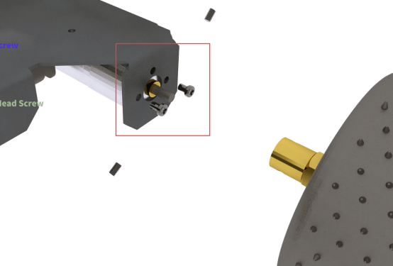
Install the rear wheel. Install the motor on the bottom of the aluminum alloy, and use M3*4 screws to pass through the aluminum alloy to fix the motor.
|
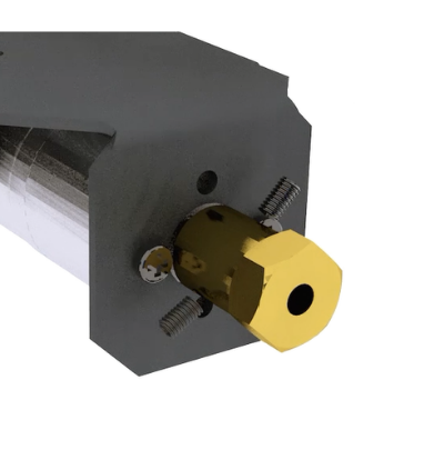
Install the inner 4mm coupling and fix it with screws.
|
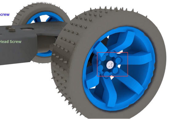
Install the rear wheel. Use M2.5*4 countersunk screws to fix.
|
Install the OLED screen. Use M2*8 screws to pass through the aluminum alloy and OLED and fix them with M2 nuts.
|
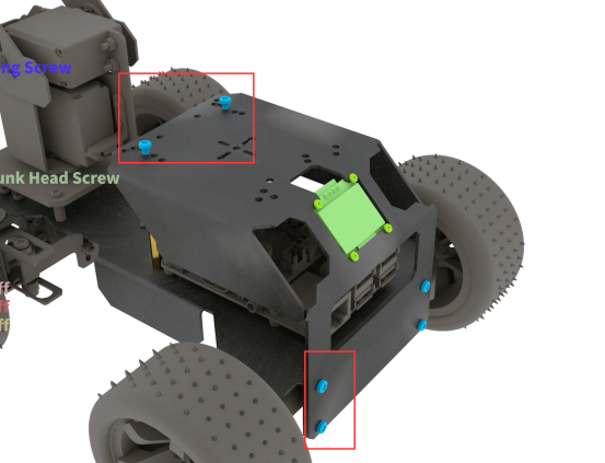
Use M3*4 screws to fix the M3*60 copper column with aluminum alloy, and use M3*4 screws to fix the aluminum alloy.(Before installing this structure, please connect the parts to Robot HAT according to "Circuit Wiring Diagram")
|
|
Installing the robotic arm
Use M3*10 screws to fix the position of the robot arm, and use two M1.7*6*6 self-tapping screws to fix the direction of the robot arm. Use M3 lock nut to fix the other end.
|
The installation is complete.
|
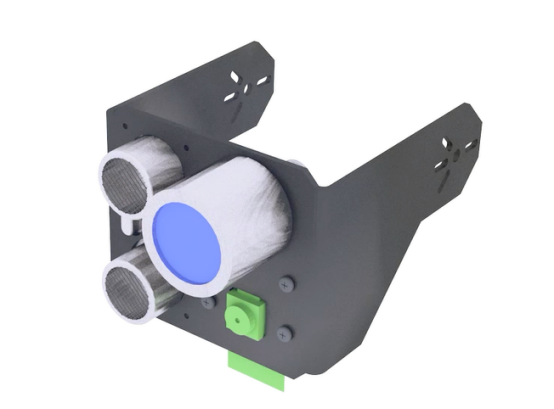
Install Ultrasonic Mode
When using the ultrasonic mode, the camera installation method is the same as the PTZ installation method. Because the shovel is equipped with a camera, when the ultrasonic mode is selected, the camera on the PTZ must be removed and installed in the designated position.
Use M1.4*6 to install the ultrasonic, and use M2*8 screws to pass through the aluminum alloy, M2 nut, camera, and M2 nut in turn (8 M2 nuts are required to install the camera). Install large LED lights. (Note: In the new version of the kit, the M1.4*6 self-tapping screws for installing the ultrasonic module are changed to M1.6*10 screws and fixed with M1.6 nuts. ) |
|
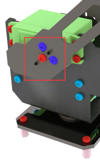
Install ultrasonic mode. It is the same as the method of installing the robot arm. Use M3*10 screws to fix the position of the robot arm, and use two M1.7*6*6 self-tapping screws to fix the direction of the robot arm. Use M3 lock nut to fix the other end.
|
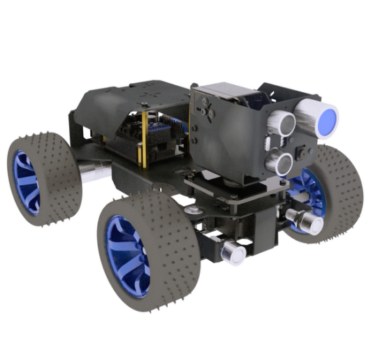
The installation is complete.
|
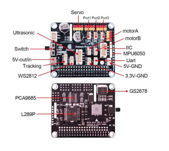
Circuit Wiring Diagram
Robot HAT board interface diagram
|
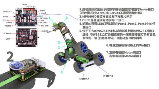
1. If you don't know how to connect the camera, you can refer to the official documentation of the Raspberry Pi camera. 2. The motor on the left is connected to the MOTOR-B port; the motor on the right is connected to the MOTOR-A port. 3. The bottom servo that controls the left and right steering of the PiCarPro car is connected to the port0 servo port of the drive board. 4. Control the servo that swings the PTZ assembly to the left and right, and connect to the Port 1 servo port of the drive board. 5. The servo that controls the robotic arm or ultrasonic swing up and down on the PTZ is connected to the Port 2 servo port. 6. The servo that controls the up and down movement of the chuck is connected to the Port 3 servo port. 7. The servo that controls the clamping action of the chuck is connected to the Port 4 servo port. 8. The ultrasonic module is connected to the Ultrasonic port with a 4pin wire. Never connect the ultrasonic to the IIC port, which will cause permanent damage to the ultrasonic module. 9. The WS2812 light bar is connected to the WS2812 port with a 3pin wire. Note here that the signal to control the light is sent by the Raspberry Pi and sent to the WS2812 light bar with the 3PIN wire with the driver board. It needs to be connected from the light bar with a white stripe. (The interface text on the back of this end is marked IN), connect from the other end of the light bar (the interface is marked OUT) and then connect to the input end of the next light bar with the 3PIN wire (It is painted with white stripes, and the interface is marked with IN). 10. The OLED screen is connected to the IIC port of the driver board with a 4PIN wire. 11. MPU6050 is inserted into the 8PIN DuPont port on the front of the driver board. 12. The two front LED lights can be connected to any interface in Port1, Port2, and Port3 (the large LED light in ultrasonic mode is connected to the remaining interface). 13. Connect the power supply to the VIN port.
|
|