Assembly Tutorial
There will be a layer of protective paper on the acrylic board, please tear it off before installation.
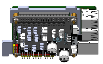
Plugging the Robot HAT into the Raspberry Pi
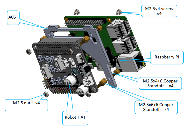
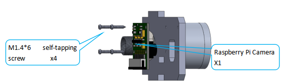
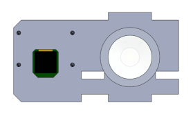
Assemble Raspberry Pi, Robot HAT, and A05.(The Raspberry Pi is not included in the kit.)
|
|
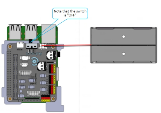
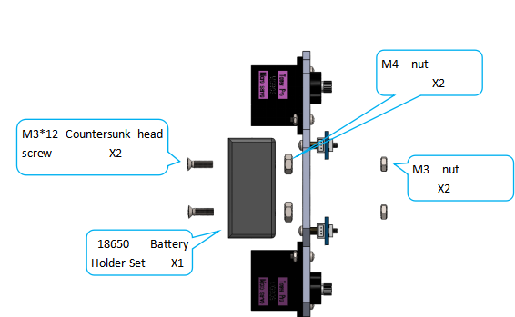
Connect the 18650 Battery Holder Set to the Adeept Robot HAT.
|
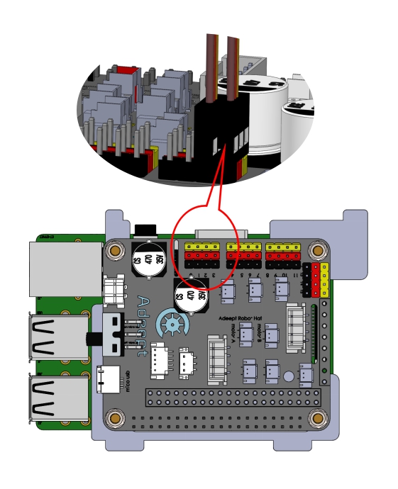
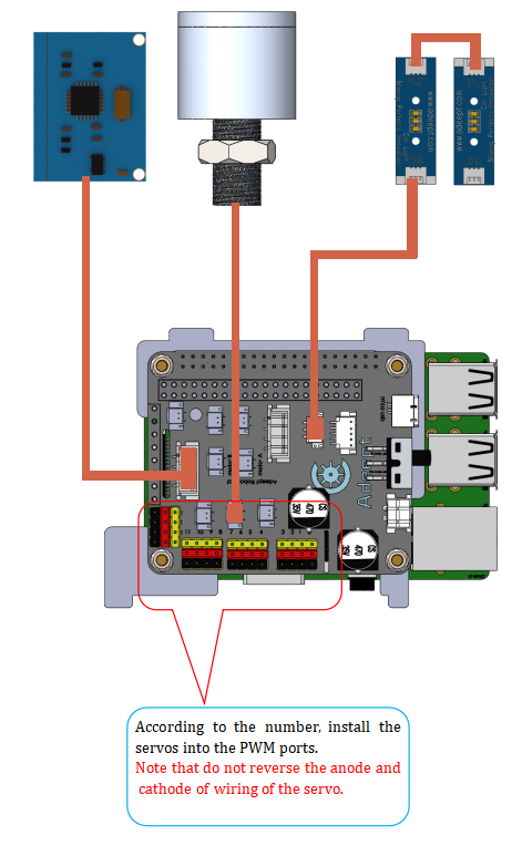
Connect the servos to Adeept Robot HAT. And the Raspberry Pi will automatically adjust the servo to the designated angle. The yellow wire is connected to the yellow pin, the red wire to the red pin, and the brown wire to the black pin. See "Precautions for Assembly" for detailed steps. If you have already adjusted the initial angle of the servo, please skip this process.
|
Assembling Legs
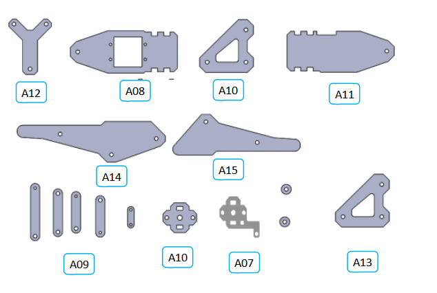
Acrylic plates needed:
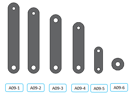
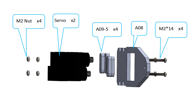
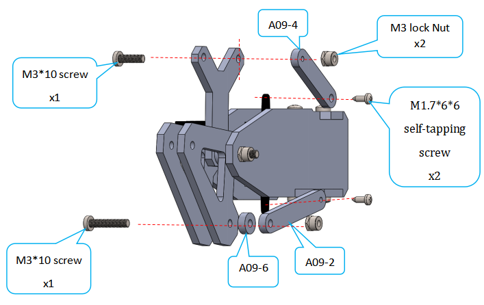
Subdivide A09, standard: length, hole size. A09-1: The longest length (about 46mm) A09-2: The second length, with 1 large hole and 1 small hole (about 42mm) A09-3: The third length, with 2 large holes (about 38mm) A09-4: The fourth length, with 1 large hole and 1 small hole (about 33mm) A09-5: The shortest length (about 17mm) It is recommended to classify A09 into categories before assembly to avoid misuse during installation.
|
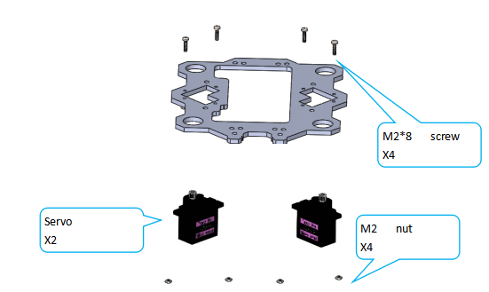
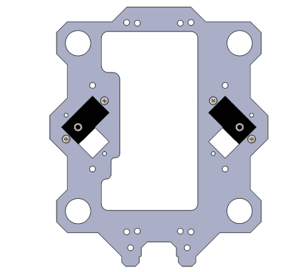
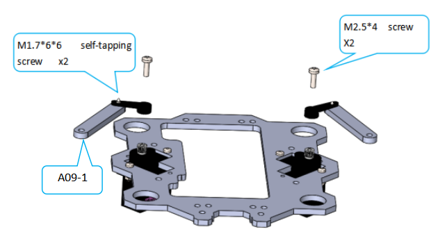
Fix the servo on the acrylic plate.
|
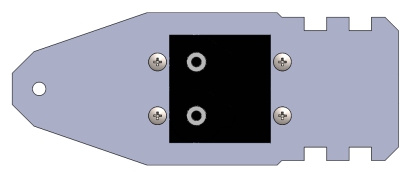
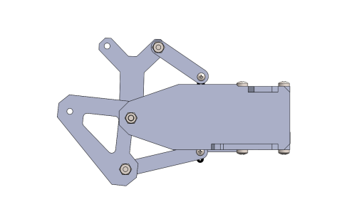
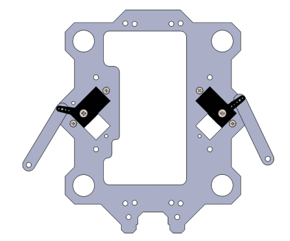
Effect diagram after assembling:
|
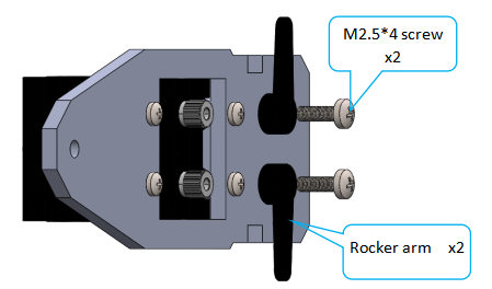
Install the rocker arm on the servo. Please note that the servo is connected to the Raspberry Pi robot HAT, install the rocker arm at the angle as shown in the picture.
|
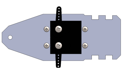
Effect diagram after assembling
|
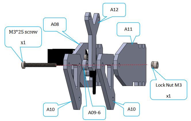
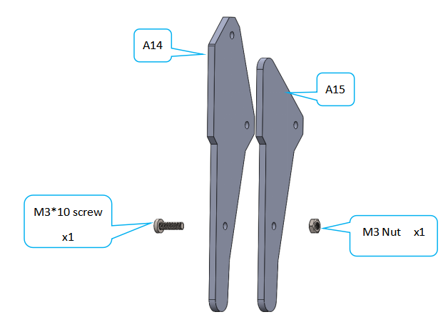
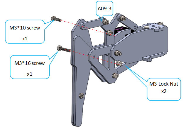
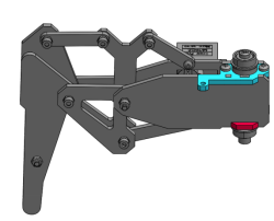
Assemble the following components Note: When assembling the other 3 legs, the placement angle of A11 will change. Install other parts according to the comparison diagram. For details, please refer to the comparison chart of the 4 legs.
| ||||
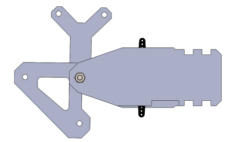
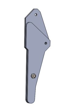
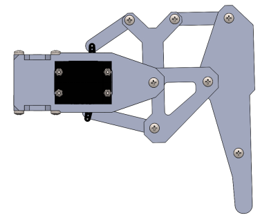
Effect diagram after assembling
| ||||
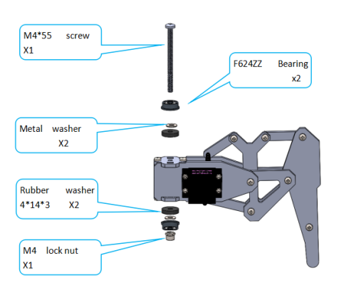
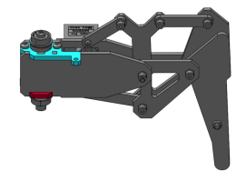
Assemble the following components Note: The other three legs will be in different positions depending on the installation direction of A11. See comparison chart for details.
| ||||
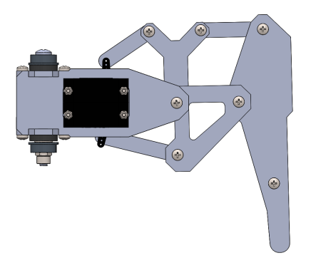
Effect diagram after assembling
| ||||
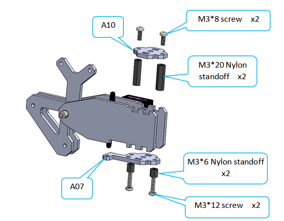
Assemble the following components
| ||||
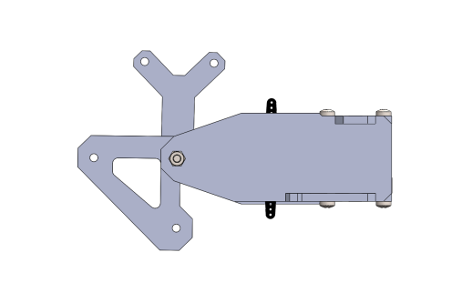
Effect diagram after assembling
| ||||
|
Effect diagram after assembling
|
|
Effect diagram after assembling
|
|
Effect diagram after assembling
|
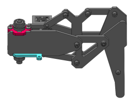
According to the installation direction of A11, assemble 3 different feet (the above steps assembled No:1)
Comparison chart of four legs
No:1
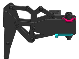
| No:2
|
|
|
Each leg is installed in a different way. Please install each robot leg according to the above installation angle.
| |
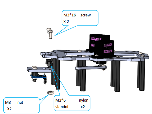
Assembling the Base of the Body
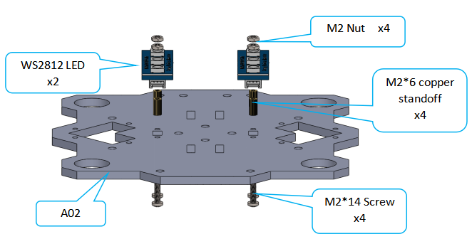
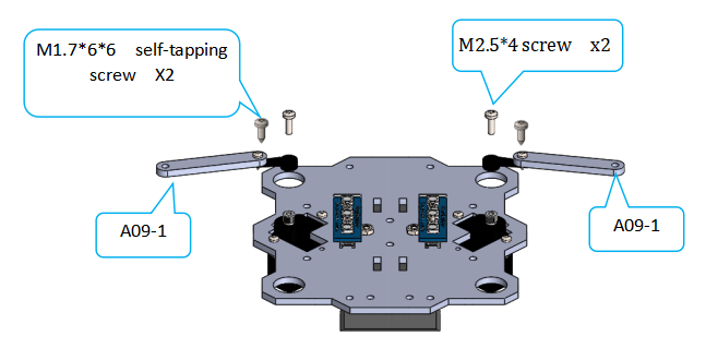
Assemble the following components The "IN" interface of the WS2812 module receives the Raspberry Pi electrical signal, and the "OUT" interface outputs the electrical signal to other WS2812 modules. (Please connect the circuit between multiple WS2812 LEDs before installation.)
|
|
|
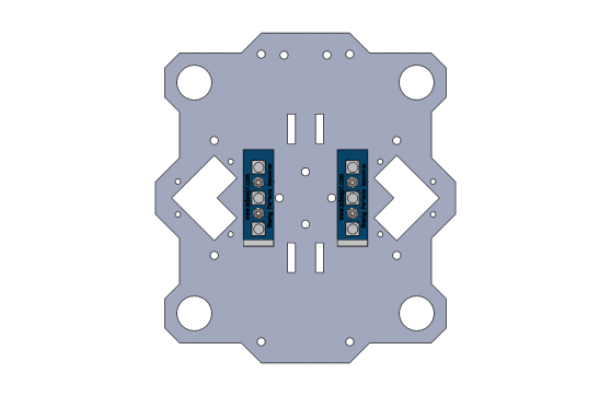
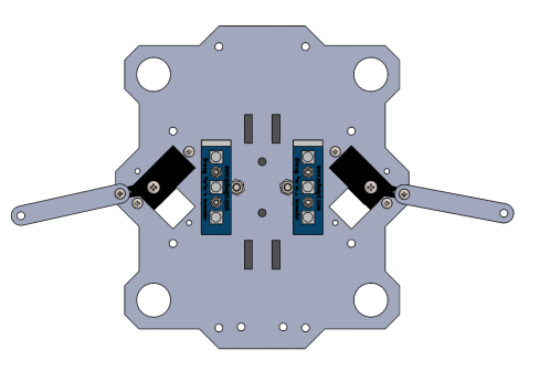
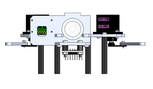
Effect diagram after assembling
|
|
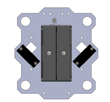
Effect diagram after assembling The hole position of the battery box will be different, please install the screws according to the hole position of the battery box in the product.
|
|
Effect diagram after assembling
|
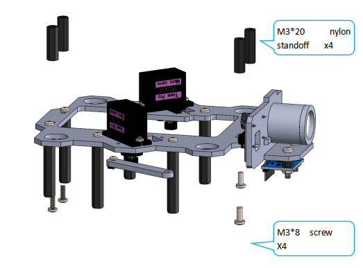
Assemble the other parts of the body.
|
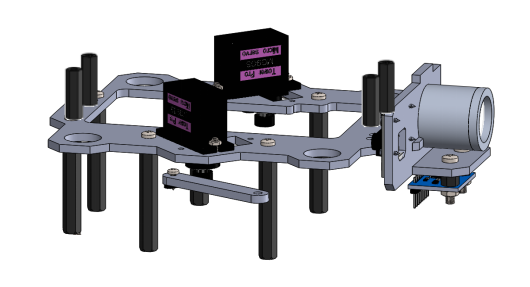
Effect diagram after assembling
|
|
Effect diagram after assembling
|
|
Effect diagram after assembling.
|
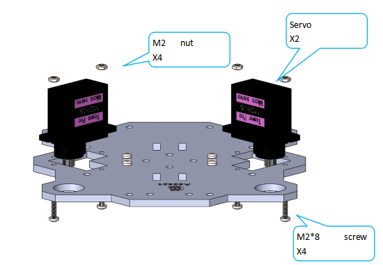
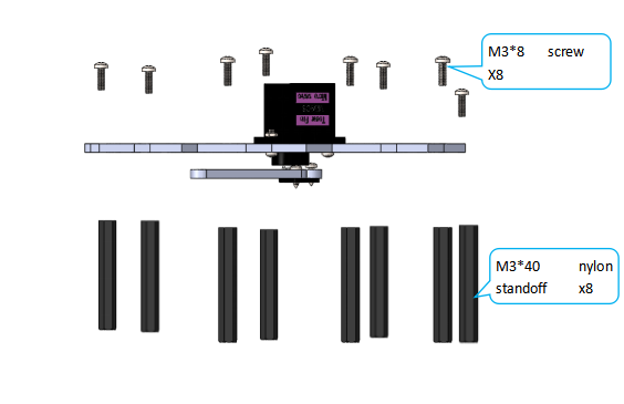
Install the servos.
|
|
|
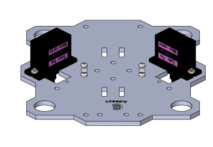
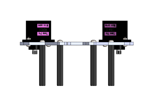
Effect diagram after assembling
|
|
Effect diagram after assembling
|
|
Effect diagram after assembling
|
|
Effect diagram after assembling
|
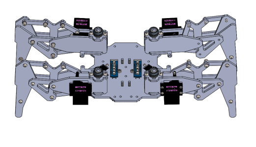
Assemble all the parts finished above.
|
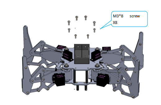
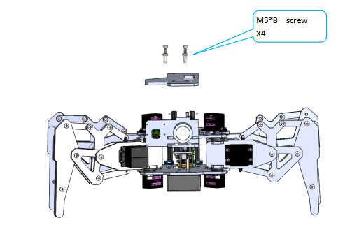
Assemble the following components
|
|
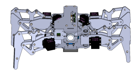
Effect diagram after assembling
|
Before installing the Raspberry Pi, please connect the circuit according to the circuit connection diagram below.
|
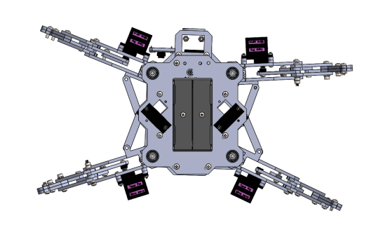
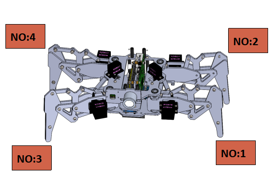
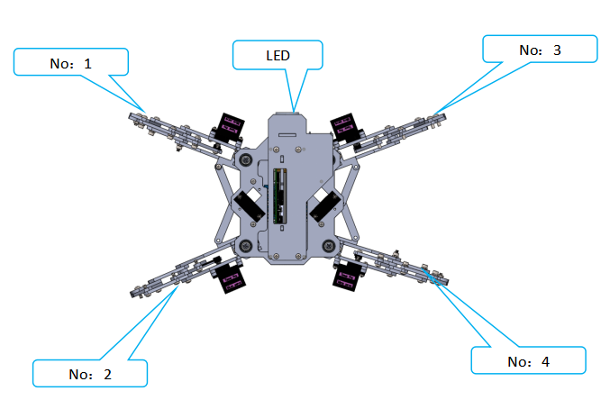
The numbering of the 4 feet is consistent with the numbering in the foot comparison picture. (The direction of the steering gear is towards the surroundings)
|
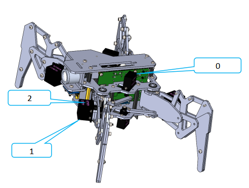
| Each leg needs to occupy 3 servo ports, No.1: 0, 1, 2 No.2: 3, 4, 5 No.3: 6, 7, 8 No. 4: 9, 10, 11 Servos on the body in each leg , connected to the relatively smallest servo ports, The upper servo of each leg is connected to the relatively largest servo port. For example, the servo port of the No: 1 leg : The servo on the body is connected to the servo port 0 on the Robot HAT, The lower servo of the leg is connected to the servo port 1, And the upper servo of the leg is connected to the servo port 2. (NOTE: The top acrylic board is installed after the circuit is properly connected.)
Connect the three servos on the other legs to the Robot HAT.
|
|
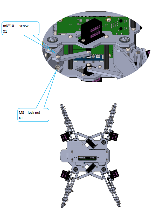
Connect the rocker arm to the leg.
|
|
|
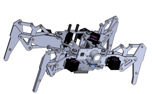
The installation is completed for the DarkPaw robot now. Note: It's recommended to use an 18650 battery that supports a maximum output current of at least 4A, or one with "high discharge rate ". |
Install and Remove Batteries
Take out 2 ribbons and 2 batteries.
|
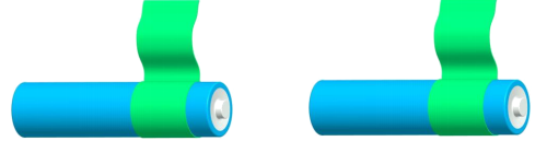
Roll one end of the ribbon to let through a battery and fix.
|
Insert the batteries into the rings-ribbon closer to the anode.
|
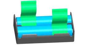
Install the batteries into the holder based on the pole.
|
To remove the batteries, just pull the ribbon and take them out.
|