Assembly tutorial
Robotic arm assembly
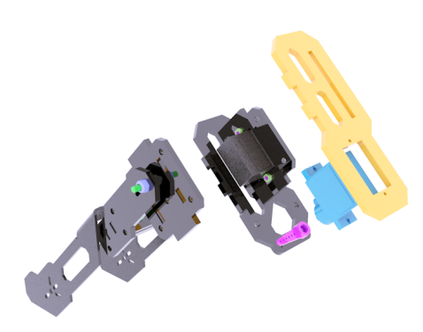
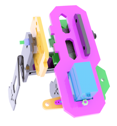
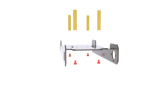
Prepare the following structure.
|
Use two M3X16 screws and two M3 nuts to fix the three acrylic panels shown above on the aluminum alloy base of the robotic arm.
|
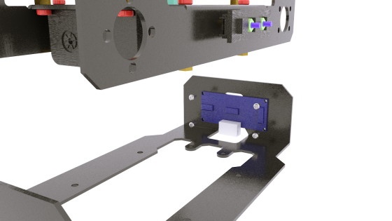
Prepare the acrylic panel shown on the right side of the above picture. There is no need to fix it on the assembled component. Since the acrylic panel on the right has directions, the rendering diagram will fix it on the component to indicate the subsequent assembly position.
|
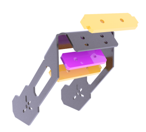
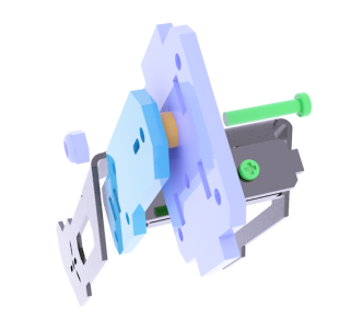
Prepare the acrylic panel and acrylic gasket as shown in the picture above.
|
Use M3X16 screws and M3-LOCK lock nuts to fix the acrylic panel and acrylic washer as shown in the figure on the side panel. It should be noted that the lock nut should not be tightened too tightly, because this is the rotating pair of the movable part. After tightening, it will not be able to rotate and the servo will be blocked. Note: All lock nuts involved in this document should not be tightened.
|
|
|
|
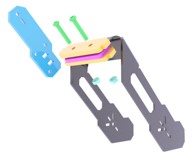
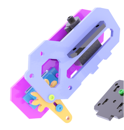
Use M2X8 screws and M2 nuts to fix the AD002 servo on the acrylic panel shown in the figure above. The acrylic panel here is similar in shape to the acrylic panel just installed, except that there are more mounting holes for fixing the servo.
|
|
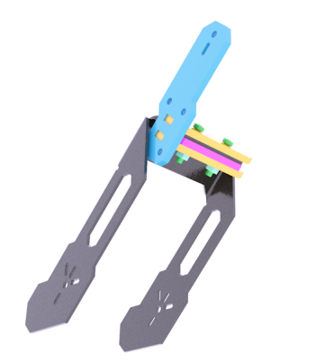
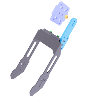
It looks like the picture above after installation. Prepare the acrylic panel (top panel of GRIPPER) and AD002 servo as shown in the picture. Use M2X8 screws and M2 nuts to fix AD002 servo to the upper panel of the arm chuck.
|
|
|
Assemble the upper panel and lower panel of the chuck. Here you can load the gear shown above between the servo arm and the lower panel. For the time being, you don’t need to fix it. You only need to know that the gear is installed here. The gear is clamped in this position to avoid the gear cannot be installed due to too small gap after assembly.
|
Use M2.5*12 screws and M1.7*6*6 self-tapping screws to fix.
|
|
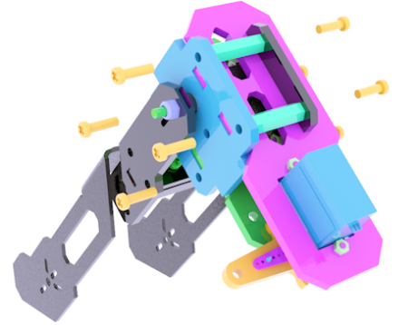
Use four M3X20 nylon posts and eight M3X10 screws to fix the left and right panels of the chuck together.
|
|
|
|
|
|
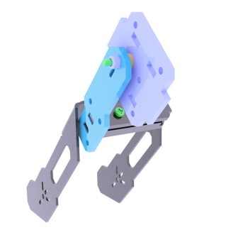
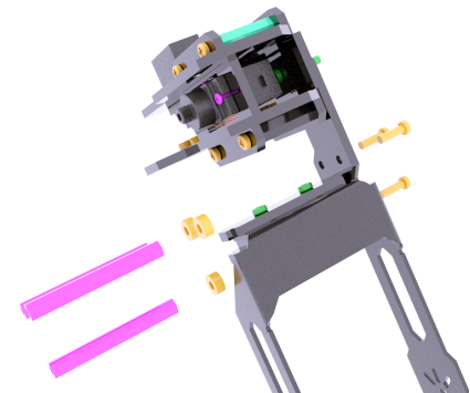
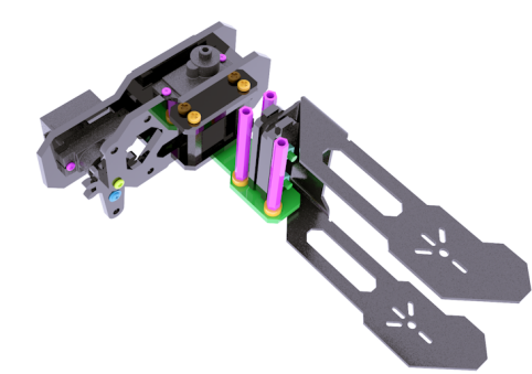
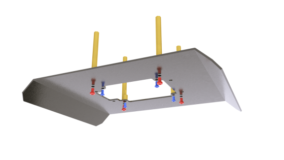
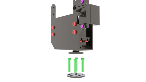
Use three M3X10 screws to fix the acrylic washer and M3X40 nylon column to the side panel of the robot arm.
|
|
|
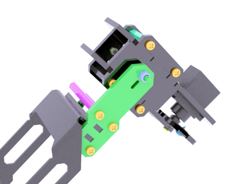
Use three M3X10 screws to fix the panel on the other side. Use M1.7X6X6 self-tapping screws to fix the side panel and the servo arm, and use M2.5X8 screws to fix the servo to the side panel.
|
|
|
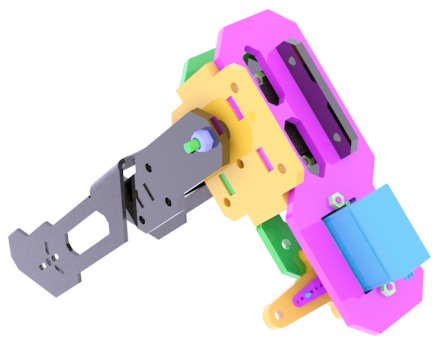
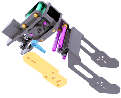
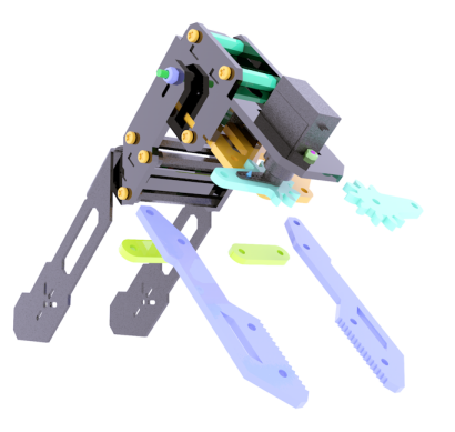
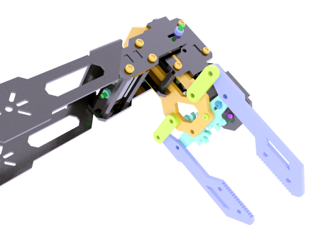
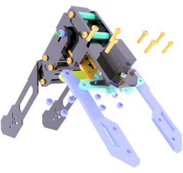
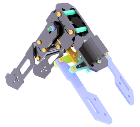
The assembled look is shown in the figure above. Prepare the gear on the other side and the connecting rod parts for the chuck.
|
|
|
|
|
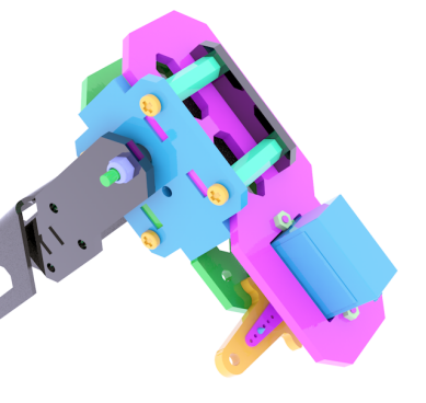
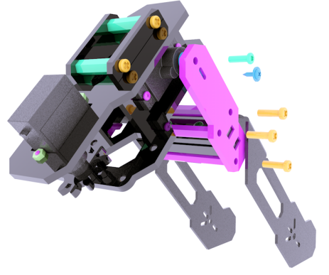
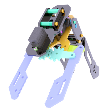
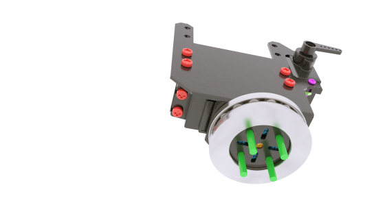
The installation method is shown in the figure above. Use M3X10 screws and M3-LOCK locknuts to assemble the connecting rods.
|
|
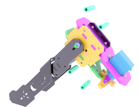
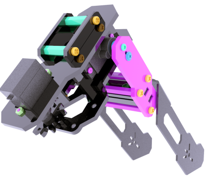
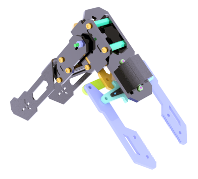
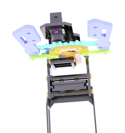
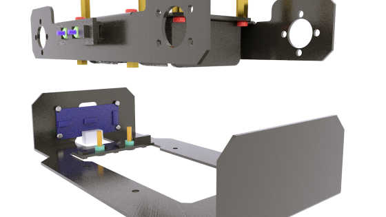
The robot arm after assembly is as shown in the figure above. |
Body assembly
Prepare the following components.
|
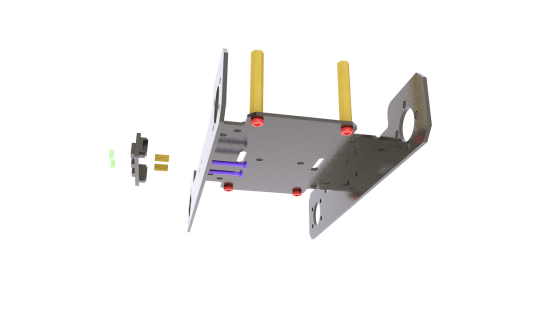
Use M3X4 screws to fix the M3X30 on the aluminum alloy base. The specific installation location is shown in the figure below.
|
Use M2X14 screws to pierce through the side panel of the aluminum alloy base,then pierce through M2X6 copper posts and WS2812 light bar, and use M2 nuts to fix.
|
The light bar on the other side is installed as above.
|
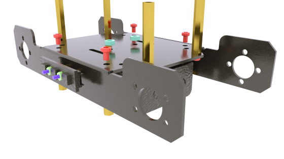
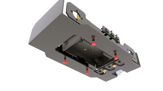
Use M3X4 screws to fix the M3X20 copper column on the aluminum alloy base, and use M3X6 countersunk head screws and M3 nuts to fix the battery holder on the aluminum alloy base. The fixed position is shown in the figure below.
|
The picture above shows the fixed position of the M3X20 copper column and the battery holder.
|
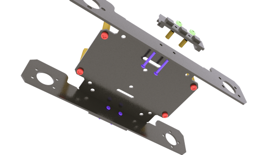
Use M1.4X6 self-tapping screws to fix the ultrasonic module on the lower plate.
|
Use M3X10 screws and M3 nuts to fix the tracking module on the lower plate. Note that the arrow on the tracking module needs to point to the front of the robot to install.
|
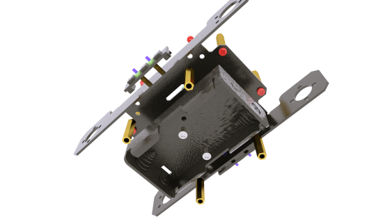
Use M3X4 screws to fix the lower plate to the base.
|
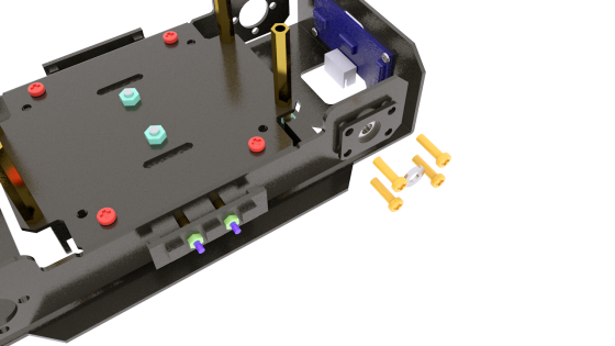
Install the F624ZZ bearing to the base.
|
Use M3X10 screws to fix. Prepare the metal gasket as shown in the picture, and install it between the bearing and the wheel.
|
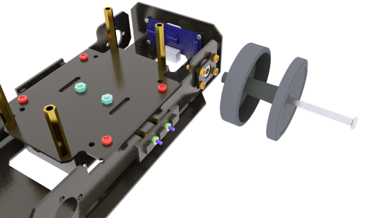
Use M4X45 screws to install the wheels.
|
Use M4-LOCK lock nuts to fix the wheels. Note that the spacers as shown in the figure also need to be installed between the lock nuts and the bearings.
|
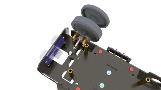
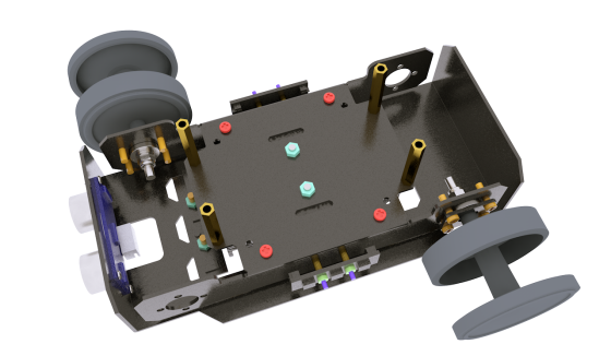
It looks like the picture after installation.
|
|
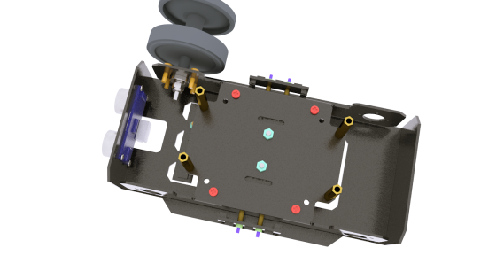
Use the same method to install the bearings and wheels on the other side.
|
Install the motor and the coupling. The coupling screws need to be tightened. Use M3X4 screws to fix the motor to the base.
|
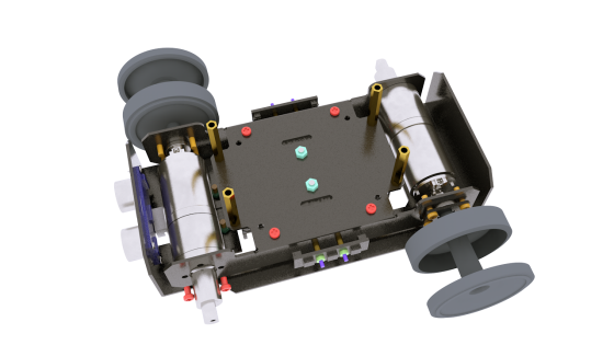
Use the same method to install the motor on the other side.
|
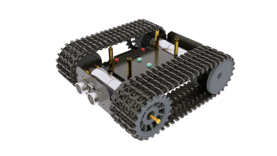
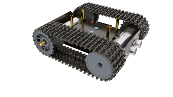
Install tracks on both sides.
|
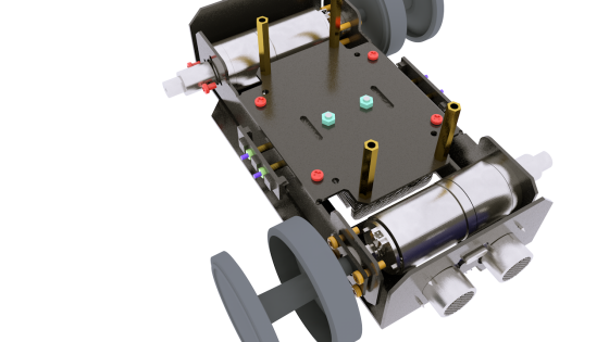
Use M3X10 screws to fix the wheel to the coupling.
|
The installation method is the same on the other side.
|
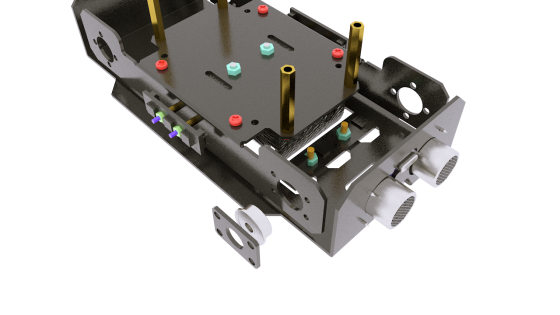
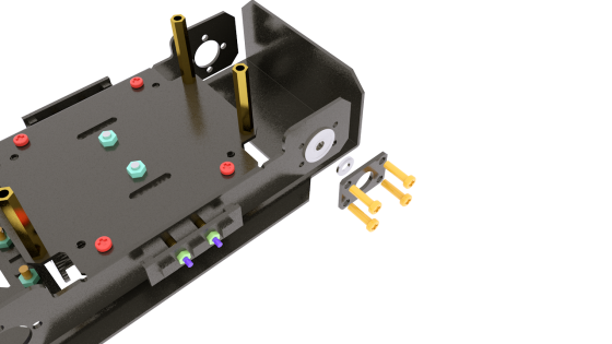
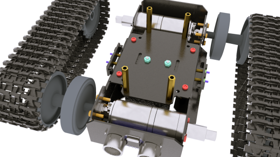
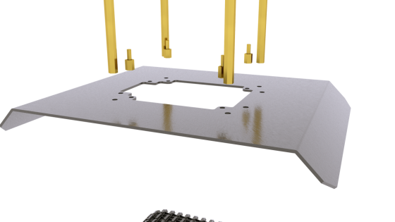
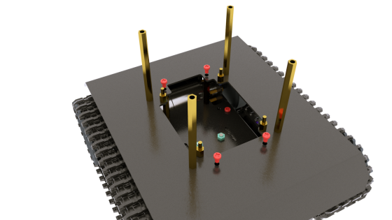
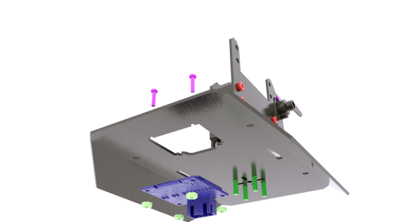
Use M3X4 screws and M2.5X4 screws to fix the M3X60 copper posts and M2.5X6+6 copper posts on the upper section. The specific fixing position is shown in the figure below.
|
The installation location is shown in the figure.
|
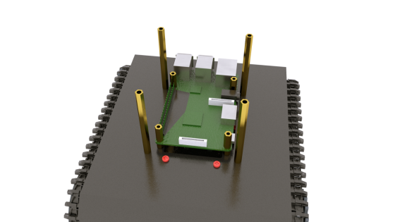
Use M3X4 screws to fix the upper plate to the base.(The Raspberry Pi is not included in the kit.)
|
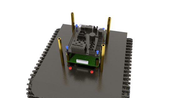
Use M2.5X14 copper posts to fix the Raspberry Pi to the base. At this time, you need to connect the camera cable to the Raspberry Pi. Use M2.5X4 screws to fix the Robot HAT driver board to the Raspberry Pi.
|
PTZ assembly
|
|
Use M3X4 screws to fix the servo to the servo bracket as shown in the two pictures above. The servo bracket has tapped threads, so no nuts are needed for installation here.
|
Use M3X4 screws to fix the servo bracket to the PTZ base.
|
Use M2X8 screws and M2 nuts to fix the AD002 servo to the base of the PTZ.
|
Install the round rocker arm of the large metal servo, and pierce the M3X16 screws through the round aluminum alloy parts shown below.
|
Use M1.7X6X6 self-tapping screws and M3X10 screws to fix the round aluminum alloy parts to the servo rocker arm and servo. 【Attention】:
|
|
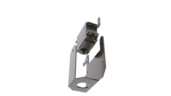
Then install a round aluminum alloy part, and then install 51105 thrust bearing.
|
Install the 51105 thrust bearing. Note here that the thrust bearing consists of three separate parts. Subsequent assembly will compress the thrust bearing.
|
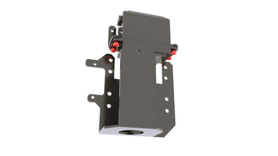
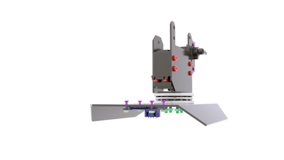
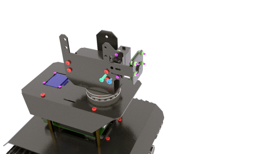
Install the PTZ base assembly to the section below the PTZ. Use M2X8 screws and M2 nuts to install the OLED screen.
|
Use the M3 nut to fix the PTZ base assembly to the lower section. The side view is shown in the figure above. After tightening the nut, the thrust bearings are fixed together and the PTZ base assembly can rotate normally.
|
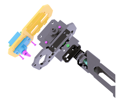
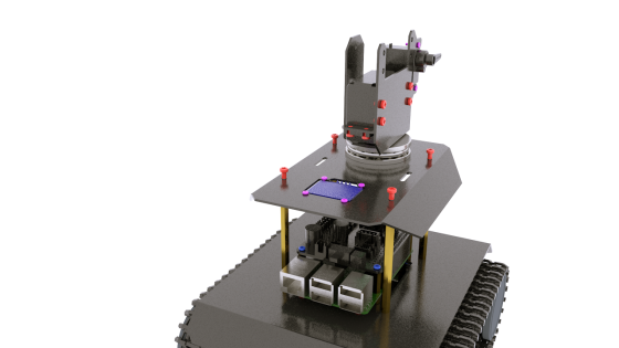
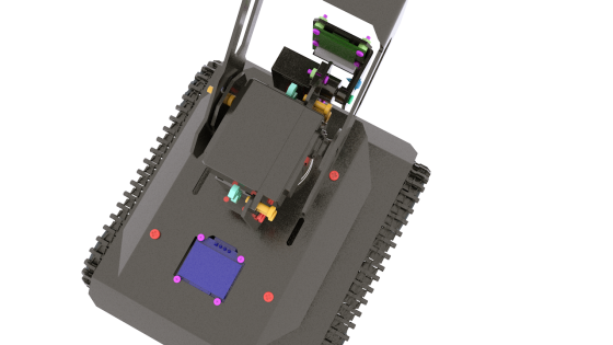
Use M3X4 screws to fix the upper plate assembly to the body assembly. Before performing this step, you need to connect the cable. Refer to the wiring method chapter for details.
|
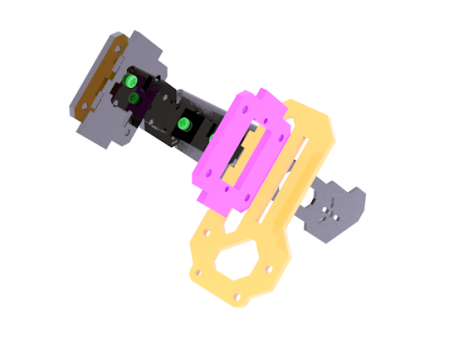
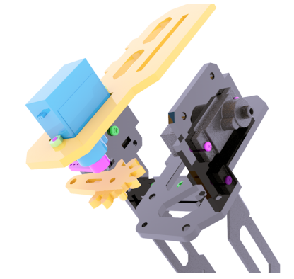
Use 4 M2X8 screws and 8 M2 nuts to install the Raspberry Pi camera to the aluminum alloy camera bracket. Use M2.5X8 screws and M1.7X6X6 self-tapping screws to fix the aluminum alloy camera bracket to the servo rocker arm and servo.
|
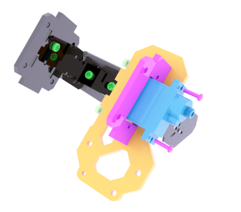
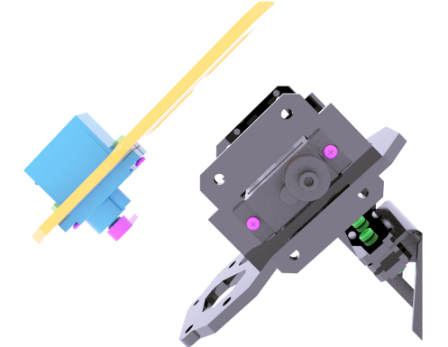
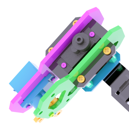
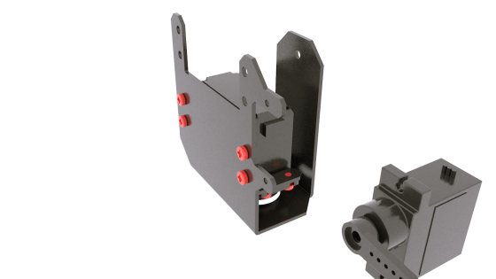
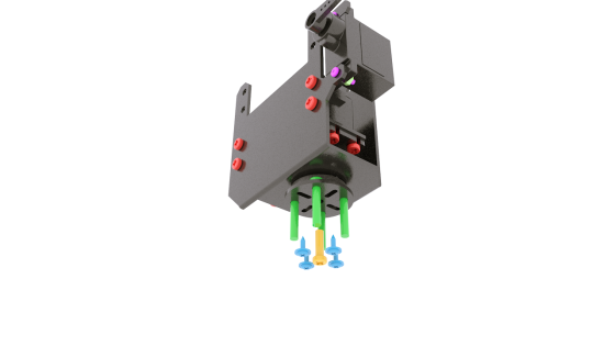
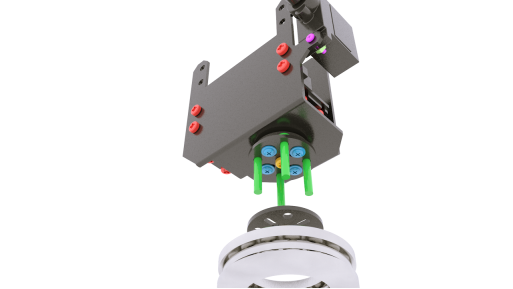
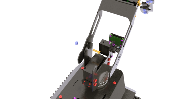
Use M3X10 screws and M3-LOCK lock nuts to fix the robot arm to the base of the PTZ. Note here that the lock nuts cannot be tightened too much, otherwise it will affect the rotation of the robot arm assembly.
|
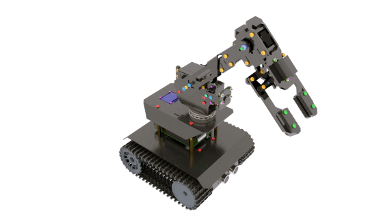
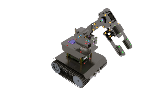
After the installation is complete, as shown above.
|
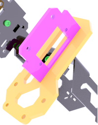
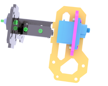
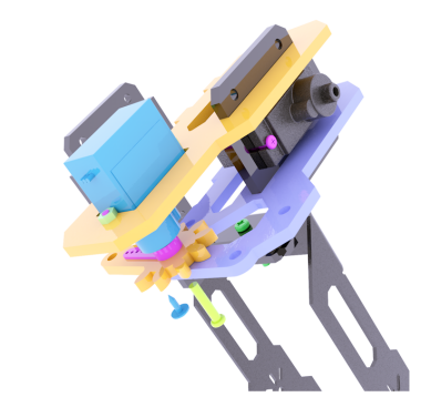
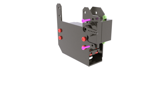
Use M3X10 screws and M3 nuts to fix the servo to the base of the PTZ.
|
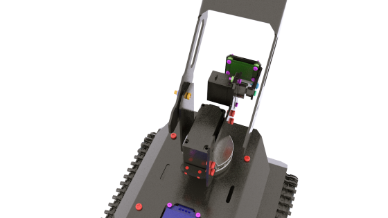
Use M3X10 screws and M1.7X6X6 self-tapping screws to connect the robot arm to the PTZ base.
|
The assembly is complete. |
Wiring method
l If you don’t know how to connect the camera, you can refer to the official documentation of the Raspberry Pi camera.
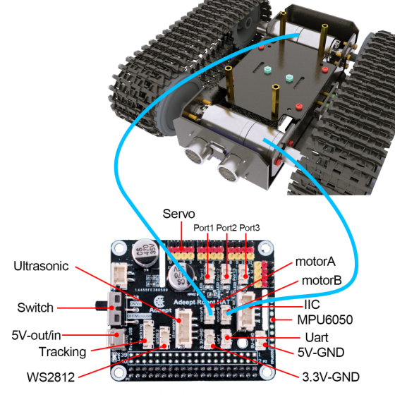
l The motor on the left is connected to the MOTOR-B port; the motor on the right is connected to the MOTOR-A port.
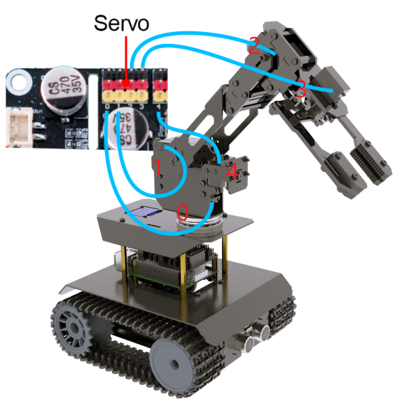
l The bottom servo that controls the pan/tilt component to swing left and right is connected to the Port 0 servo port of the driver board.
l There are two servos that control the mechanical arm to swing up and down. One is large and one is small. The large servo fixed on the PTZ assembly is connected to the Port 1 servo port, and the small servo fixed in the middle of the mechanical arm is connected to Port 2 Servo port.
l The servo that controls the gripping action of the chuck is connected to the Port 3 servo port.
l The servo that controls the tilting motion of the camera is connected to the Port 4 servo port.
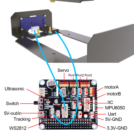
l The ultrasound module is connected to the Ultrasonic port using a 4pin cable. Never connect the ultrasound to the IIC port, as the ultrasound module will be permanently damaged.
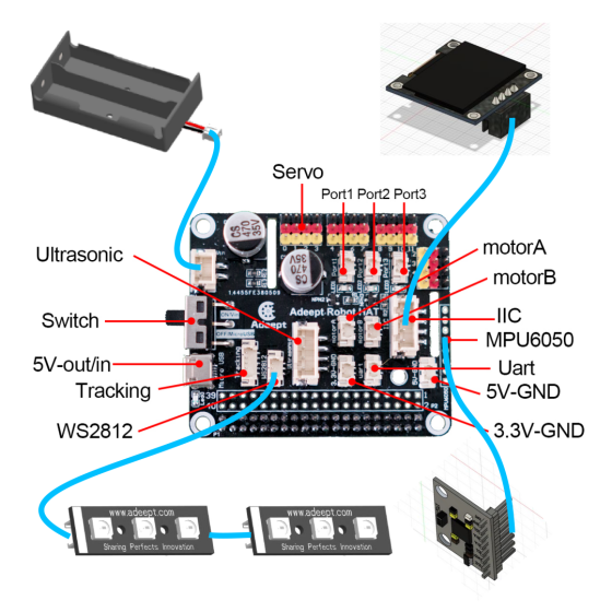
l The WS2812 light bar is connected to the WS2812 port using a 3pin cable. Note here that the signal to control the light is sent by the Raspberry Pi and sent to the WS2812 light bar by the 3PIN line by the driver board. A section with white stripes drawn from the light bar needs to be connected ( The text of the interface on the back of this end is marked with IN). Take it out from the other end of the light bar (the interface is marked OUT) and connect it to the input end of the next light bar by the 3PIN line (the white stripe is drawn and the interface is marked with IN).
l The OLED screen is connected to the IIC port of the driver board via a 4PIN cable.
l MPU6050 is inserted into the 8PIN Dupont port on the front of the driver board.
l The power supply is connected to the VIN port.
l The tracking module is connected to the Tracking port via a 5PIN wire.