Lesson 5 How to Use the Tracking Function
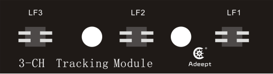
5.1 Tracking module
The "road"-the black line can be judged according to the reflected light received on the white paper "road" with black lines because of the different reflection coefficients of light between black lines and white paper. A more common detection method-infrared detection method is adopted in the tracking module.
Infrared detection is the method that makes use of infrared rays with reflection features on different physical surfaces in different colors. When the trolley is running, it continuously emits infrared light to the ground. That the infrared light comes across the white ground will cause
diffuse reflection, and the reflected light is received by the receiving tube on the trolley; when it coming across a black line, it will be absorbed by the infrared light, and the trolley receiving tube fails to receive the signal.
5.2 Preparation
1.Assemble the completed RaspTankPro. The tracking module is fixed under the center hole of the front wheel of the RaspTankPro chassis by a 15mm nylon column with the M3*4 screws. Note: please disassemble the tracking module to avoid any damage to the tracking module, when not using the tracking function or driving on the uneven ground. (The tracking module is about 7-10mm away from the ground)
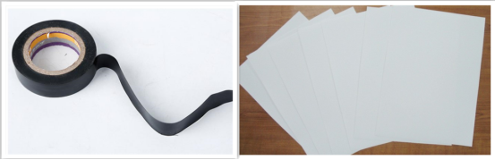
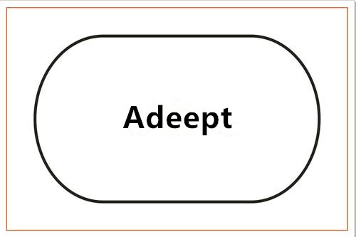
2.Prepare a tracking track. Because of the steering limitation of the front-wheel servo, the curve radius of the track should not be too small.
5.3 Turn on the tracking function
Run the tracking program
1. Start up RaspTankPro for about 1 minute.
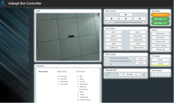
2. When RaspTankPro is started up, enter the IP address of your Raspberry Pi on the Google browser of the mobile phone or computer, and access Port 5000, for example: 192.168.3.44:5000. Then the web controller will be displayed on the browser.
1. Place the car on the completed tracking track.
2. Click "TRACK LINE", and RaspTankPro will drive along the black line.
3. Click "TRACK LINE" for a second time, if you want to terminate the tracking function.
4. The height of the tracking module and the ground will have effects on the accuracy of the detection line of the tracking module. If the tracking function fails, the tracking module should be adjusted.
5.4 The main code program
Please see the complete code in findline.py.
Import dependency and initialize
1. import RPi.GPIO as GPIO 2. import time 3. 4. line_pin_right = 19 5. line_pin_middle = 16 6. line_pin_left = 20 7. 8. def setup(): 9. GPIO.setwarnings(False) 10. GPIO.setmode(GPIO.BCM) 11. GPIO.setup(line_pin_right,GPIO.IN) 12. GPIO.setup(line_pin_middle,GPIO.IN) 13. GPIO.setup(line_pin_left,GPIO.IN) |
Define the main function of the line searching module
1. def run(): 2. status_right = GPIO.input(line_pin_right) 3. status_middle = GPIO.input(line_pin_middle) 4. status_left = GPIO.input(line_pin_left) 5. 6. # Detect whether the line searching module senses the lines 7. if status_middle == 1: 8. print('forward') 9. elif status_left == 1: 10. print('left') 11. elif status_right == 1: 12. print('right') 13. else: 14. print('stop') |
Execute the function
1. if __name__ == '__main__': 2. setup() 3. while 1: 4. run() |
5.5 Adjust the tracking module
Method 1: Adjust the accuracy of the tracking module by simulating the height after installation.
Method 2: If you don’t want to remove the Raspberry Pi, adjust the tracking module and install it on the robot product for testing. It may be debugged for several times, please keep trying.
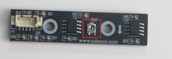
Rotate the potentiometer R10 of the tracking module for adjusting the tracking module. The steps of Method1 are as follows.
Components
Components | Quantity | Picture |
Raspberry Pi | 1 |
|
Robot HAT | 1 |
|
3 pin cable | 1 |
|
WS2812 RGB LED | 1 |
|
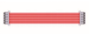
5 pin cable | 1 |
|
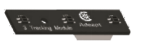
Tracking Module | 1 |
|


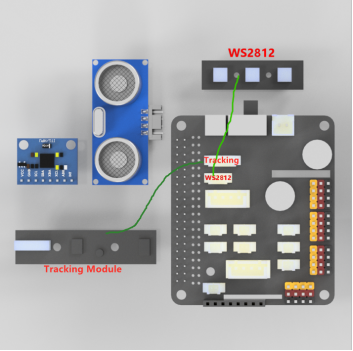
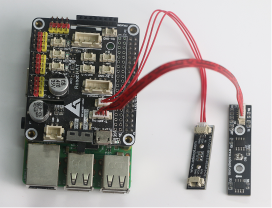
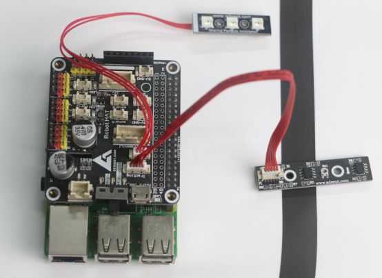
Circuit diagram (wiring diagram)
When using the WS2812 LED module, connect the IN port to the WS2812 interface on the RobotHAT driver board, as shown below:
Run the debugging program
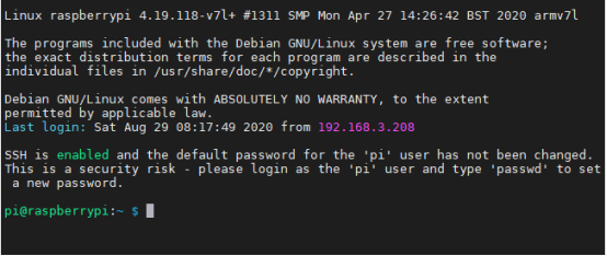
1. Log in to your Raspberry Pi via SSH:
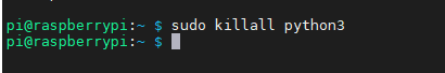
2. If your robot code is configured, the Raspberry Pi will run the webServer.py program when starting up. Please terminate the webServer.py program when running this program. The Raspberry Pi will still automatically run webServer.py when starting up for a second time and terminate the program command:
sudo killall python3
3. Download the code program, enter the following command in the console:
git clone https://github.com/adeept/adeept_trackingmodule.git

4. After completing the download, run the program trackingmodule.pyand and enter the following commands to run this program on the Raspberry Pi:
sudo python3 adeept_trackingmodule/tackingmodule.py
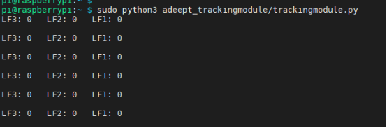
5. After running the program successfully, you will see the return values of the 3 detecting points of the tracking module. LF1, LF2 and LF3 correspond to LF1, LF2 and LF3 on the tracking module.
6. "0" refers to failing to detect the black line. "1" refers to succeeding in detecting the black line.
7. Start debugging the tracking module and place LF1 at a position about 7 ~ 10mm above the black line. When "LF3: 0 LF2: 0 LF1: 1" is returned from the console, and D1 blue light of the WS2812 LED light is on, D2 and D3 are off, it suggests that the adjustment is a success. (The height of the actual installation of the tracking module for each robot product is different, please refer to the tutorial or measure the height when completing the installation of the robot product)
8. If "LF3: 0 LF2: 0 LF1: 1" fails to show or D1 blue light is on, and D2 and D3 are off, please rotate the potentiometer R10 on the tracking module with a screwdriver until such kind of phenomenon appears. Note: the height of the tracking module and the ground will have effects on the results. Please keep the height of the tracking module stable. The potentiometer of the tracking module is shown in the figure below.
9. Test LF2 and LF3, when completing the debugging. When LF2 or LF3 is placed above the black line, D2 and D3 corresponding to the WS2812 LED will light up in blue.
10. When you want to terminate the running program after debugging, press the shortcut key "Ctrl + C" on the keyboard.
Main code program
Trackingmodule.py
1. import time 2. from rpi_ws281x import * 3. import RPi.GPIO as GPIO 4. 5. # LED strip configuration: 6. LED_COUNT = 3 # Number of LED pixels. 7. LED_PIN = 12 # GPIO pin connected to the pixels (18 uses PWM!). 8. #LED_PIN = 10 # GPIO pin connected to the pixels (10 uses SPI /dev/spidev0.0). 9. LED_FREQ_HZ = 800000 # LED signal frequency in hertz (usually 800khz) 10. LED_DMA = 10 # DMA channel to use for generating signal (try 10) 11. LED_BRIGHTNESS = 255 # Set to 0 for darkest and 255 for brightest 12. LED_INVERT = False # True to invert the signal (when using NPN transistor level shift) 13. LED_CHANNEL = 0 # set to '1' for GPIOs 13, 19, 41, 45 or 53 14. 15. 16. line_pin_right = 19 17. line_pin_middle = 16 18. line_pin_left = 20 19. 20. # Create NeoPixel object with appropriate configuration. 21. strip = Adafruit_NeoPixel(LED_COUNT, LED_PIN, LED_FREQ_HZ, LED_DMA, LED_INVERT, LED_BRIGHTNESS, LED_CHANNEL) 22. # Intialize the library (must be called once before other functions). 23. strip.begin() 24. 25. 26. def setup(): 27. GPIO.setwarnings(False) 28. GPIO.setmode(GPIO.BCM) 29. GPIO.setup(line_pin_right,GPIO.IN) 30. GPIO.setup(line_pin_middle,GPIO.IN) 31. GPIO.setup(line_pin_left,GPIO.IN) 32. #motor.setup() 33. 34. # Define functions which animate LEDs in various ways. 35. def colorWipe( R, G, B): 36. """Wipe color across display a pixel at a time.""" 37. color = Color(R,G,B) 38. for i in range(strip.numPixels()): 39. strip.setPixelColor(i, color) 40. strip.show() 41. 42. def run(): 43. status_right = GPIO.input(line_pin_right) 44. status_middle = GPIO.input(line_pin_middle) 45. status_left = GPIO.input(line_pin_left) 46. print('LF3: %d LF2: %d LF1: %d\n'%(status_right,status_middle,status_left)) 47. 48. if status_left == 1 : 49. strip.setPixelColor(0, Color(0, 0, 255)) 50. else: 51. strip.setPixelColor(0, Color(0, 0, 0)) 52. 53. if status_middle == 1: 54. strip.setPixelColor(1, Color(1, 0, 255)) 55. else: 56. strip.setPixelColor(1, Color(1, 0, 0)) 57. 58. if status_right == 1: 59. strip.setPixelColor(2, Color(2, 0, 255)) 60. else: 61. strip.setPixelColor(2, Color(0, 0, 0)) 62. 63. strip.show() 64. if __name__ == '__main__': 65. try: 66. setup() 67. while 1: 68. run() 69. pass 70. except KeyboardInterrupt: 71. colorWipe(0, 0, 0) |