Lesson 6 Controlling a Warm Color LED
In this lesson, we will learn how to control a warm color LED with Raspberry Pi.
6.1 Components & Parts
Components | Quantity | Picture |
Raspberry Pi | 1 |
|
Robot HAT | 1 |
|
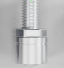
Warm Color LED | 1 |
|


6.2 About Warm Color LED
A warm color LED is an LED that can emit warm blue light when lit up (the small LED emits white light), with power 0.5W, working voltage 5V/12V, and a light-emitting angle 60°. The red line represents the positive pole and the black one, the negative pole. The small LED connects to Port 1, Port 2, and Port 3 on the Robot HAT driver board for use.
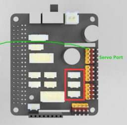
6.3 Wiring diagram (Circuit diagram)
Connect the warm color LED to the Port 1, Port 2, and Port 3 on the Robot HAT driver board, as shown in the red box:
6.4 Controlling the Warm Color LED
Run the program
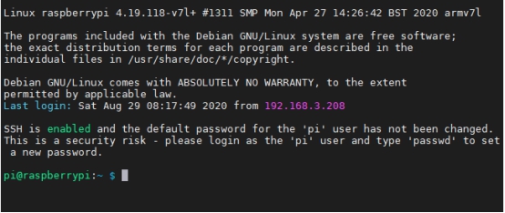
1. Log in to your Raspberry Pi via SSH (refer to Lesson 3 for more details):
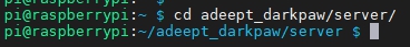
2. Type in the command to get access to the adeept_darkpaw/server folder. It includes the sample code program for controlling the robot. Type in the following command and press Enter:
cd adeept_darkpaw/server
3. Enter the command to view files under the current directory:
ls
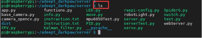
4. switch.py is a python program. You can type in the commands below to directly run it on the Raspberry Pi:
sudo python3 switch.py
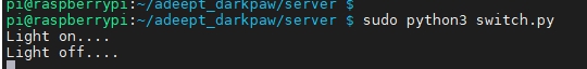
5. After successfully running the program, you can see the small warm light LED light up for 1 second and go out for 1 second. Press the shortcut "Ctrl + C" to terminate running the program.
6.5 Main Program
Refer to the switch.py file for the complete code.
1. import RPi.GPIO as GPIO 2. import time |
First import the library to control the Raspberry Pi GPIO, and instantiate it as a GPIO while importing it. Import the time library for code delay.
1. def switchSetup(): 2. GPIO.setwarnings(False) 3. GPIO.setmode(GPIO.BCM) 4. GPIO.setup(5, GPIO.OUT) 5. GPIO.setup(6, GPIO.OUT) 6. GPIO.setup(13, GPIO.OUT) |
The switchSetup() function sets the GPIO pin numbers of the Raspberry Pi corresponding to the interface to 5, 6, and 13. Here we use BCM coding method.
1. def switch(port, status): 2. if port == 1: 3. if status == 1: 4. GPIO.output(5, GPIO.HIGH) 5. elif status == 0: 6. GPIO.output(5,GPIO.LOW) 7. else: 8. pass 9. elif port == 2: 10. if status == 1: 11. GPIO.output(6, GPIO.HIGH) 12. elif status == 0: 13. GPIO.output(6,GPIO.LOW) 14. else: 15. pass 16. elif port == 3: 17. if status == 1: 18. GPIO.output(13, GPIO.HIGH) 19. elif status == 0: 20. GPIO.output(13,GPIO.LOW) 21. else: 22. pass 23. else: 24. print('Wrong Command: Example--switch(3, 1)->to switch on port3') |
The switch function sets the high and low levels of the interface. The port number represents ports 1-3. When the status is 0, the LED light connected to the corresponding interface will be turned off; when it's 1, the corresponding LED will be turned on.
1. def set_all_switch_off(): 2. switch(1,0) 3. switch(2,0) 4. switch(3,0) |
The set_all_switch_off() function sets the level of all interfaces to low, that is, to turn off the lights connected to all the ports.
1. if __name__ == "__main__": 2. switchSetup() 3. while 1: 4. switch(1,1) 5. switch(2,1) 6. switch(3,1) 7. print("Light on....") 8. time.sleep(1) 9. set_all_switch_off() 10. print("Light off....") 11. time.sleep(1) |
Instantiating the object and executing the method, function while 1 means always looping, switchSetup, switch, and set_all_switch_off means calling the above function. This section of code keeps the light on for 1 second and then shut off for 1 second.
6.6 Controlling the LED on Robot HAT Driver Board
When studying this tutorial, though the small LED module is not used, you can still learn about it by controlling the LED on the Robot HAT driver board. A green LED lies next to each interface and will light up indicating the interface is turned on.
You can observe the status of the LED on the Robot HAT driver board by referring to "6.4 Controlling the Warm Color LED" above.