Overview
In this tutorial, we will start the journey of learning Arduino MEGA 2560. In the first lesson, we will learn how to make a LED blinking.
Requirement
- 1* Arduino MEGA 2560
- 1* USB Cable
- 1* 220Ω Resistor
- 1* LED
- 1* Breadboard
- 2* Jumper Wires
Principle
In this lesson, we will program the Arduino's GPIO output high(+5V) and low level(0V), and then make the LED which is connected to the Arduino’s GPIO flicker with a certain frequency.
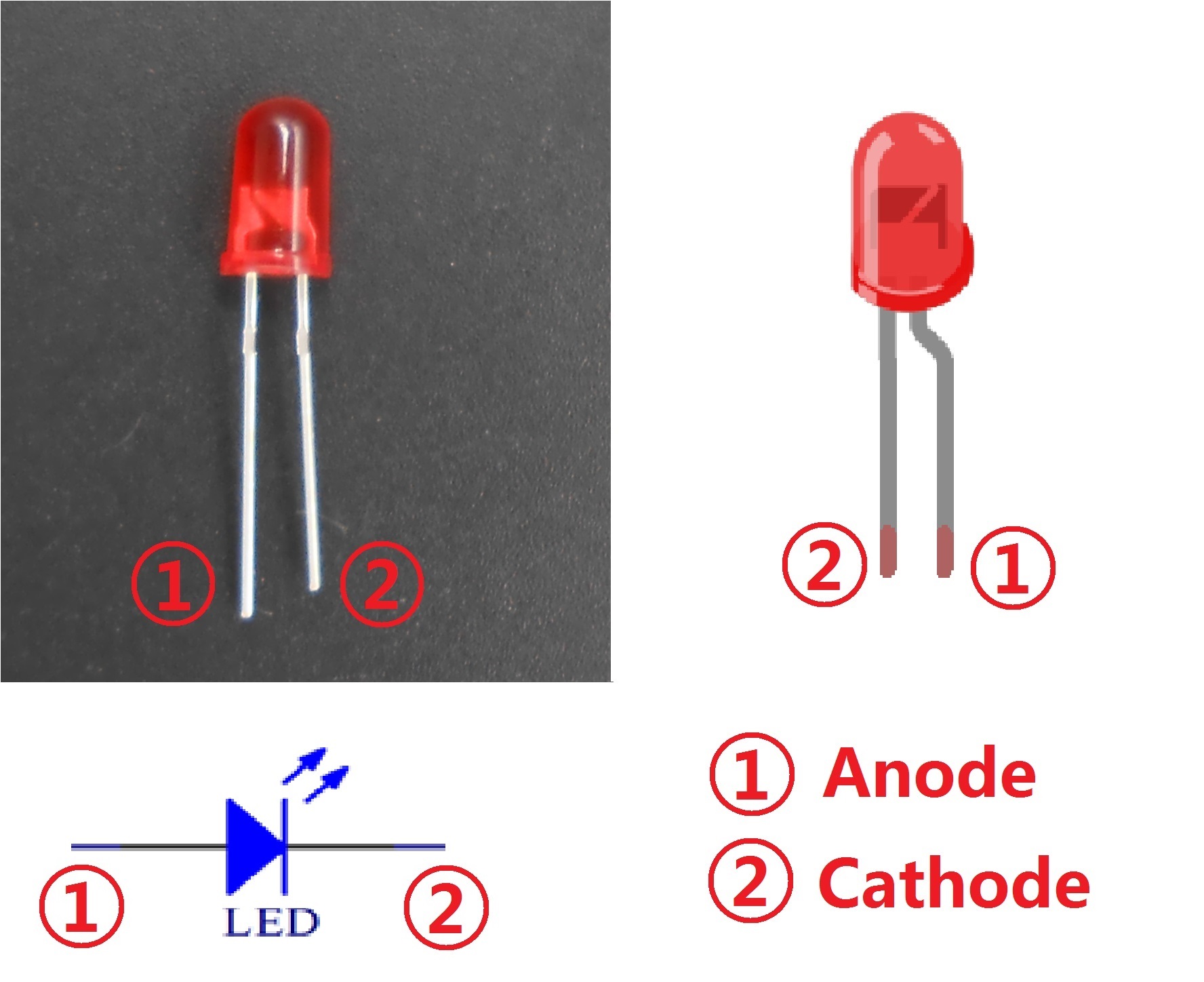
1. What is the LED?
The LED is the abbreviation of light emitting diode. It is usually made of gallium arsenide, gallium phosphide semiconductor materials. The LED has two electrodes, a positive electrode and a negative electrode, it will light only when a forward current passes, and it can be red, blue, green or yellow light, etc. The color of light depends on the materials it was made.
In general, the drive current for LED is 5-20mA. Therefore, in reality it usually needs an extra resistor for current limitation so as to protect the LED.
2. What is the resistor?
The main function of the resistor is to limit current. In the circuit, the character ‘R’ represents resistor, and the unit of resistor is ohm(Ω).
The band resistor is used in this experiment. A band resistor is one whose surface is coated with some particular color through which the resistance can be identified directly.
There are two methods for connecting LED to Arduino’s GPIO:
①

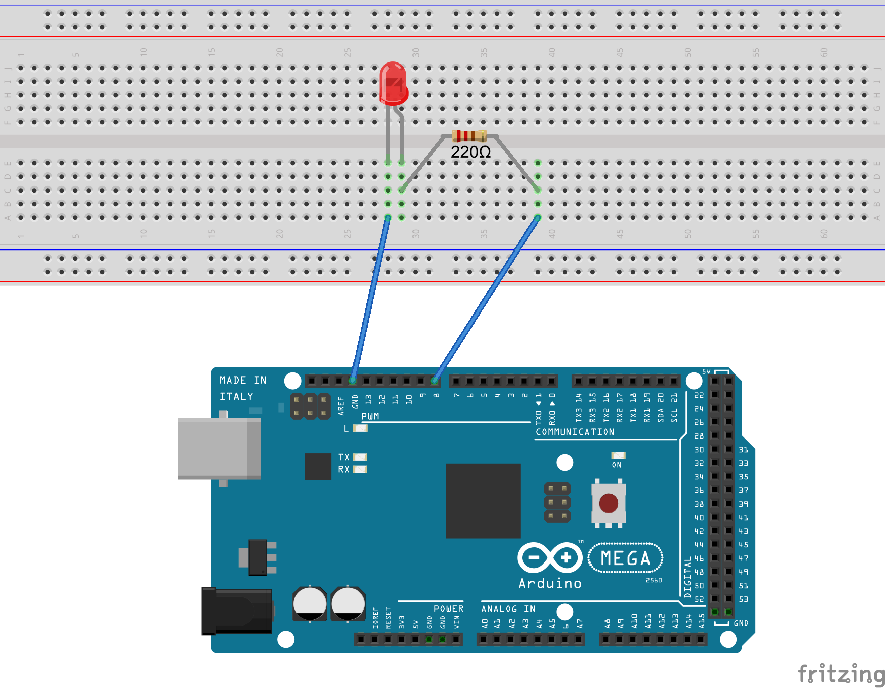
As shown in the schematic diagram above, the anode of LED is connected to Arduino’s GPIO via a resistor, and the cathode of LED is connected to the ground(GND). When the GPIO output high level, the LED is on; when the GPIO output low level, the LED is off.
The size of the current-limiting resistor is calculated as follows: 5~20mA current is required to make an LED on, and the output voltage of the Arduino MEGA 2560’s GPIO is 5V, so we can get the resistance:
R = U / I = 5V / (5~20mA) = 250Ω~1KΩ
Since the LED has a certain resistance, thus we choose a 220ohm resistor.
②

As shown in the schematic diagram above, the anode of LED is connected to VCC(+5V), and the cathode of LED is connected to the Arduino’s GPIO. When the GPIO output low level, the LED is on; when the GPIO output high level, the LED is off.
The experiment is based on method ①, we select Arduino's D8 pin to control the LED. When the Arduino’s D8 pin is programmed to output high level, then the LED will be on, next delay for the amount of time, and then programmed the D8 pin to low level to make the LED off. Continue to perform the above process, you can get a blinking LED.
3. Key functions:
● setup()
The setup() function is called when a sketch starts. Use it to initialize variables, pin modes, start using libraries, etc. The setup function will only run once, after each powerup or reset of the Arduino board.
●loop()
After creating a setup() function, which initializes and sets the initial values, the loop() function does precisely what its name suggests, and loops consecutively, allowing your program to change and respond. Use it to actively control the Arduino board.
●pinMode()
Configures the specified pin to behave either as an input or an output.
As of Arduino 1.0.1, it is possible to enable the internal pullup resistors with the mode INPUT_PULLUP. Additionally, the INPUT mode explicitly disables the internal pullups.
●digitalWrite()
Write a HIGH or a LOW value to a digital pin.
If the pin has been configured as an OUTPUT with pinMode(), its voltage will be set to the corresponding value: 5V (or 3.3V on 3.3V boards) for HIGH, 0V (ground) for LOW.
If the pin is configured as an INPUT, digitalWrite() will enable (HIGH) or disable (LOW) the internal pullup on the input pin. It is recommended to set the pinMode() to INPUT_PULLUP to enable the internal pull-up resistor.
●delay()
Pauses the program for the amount of time (in miliseconds) specified as parameter. (There are 1000 milliseconds in a second.)
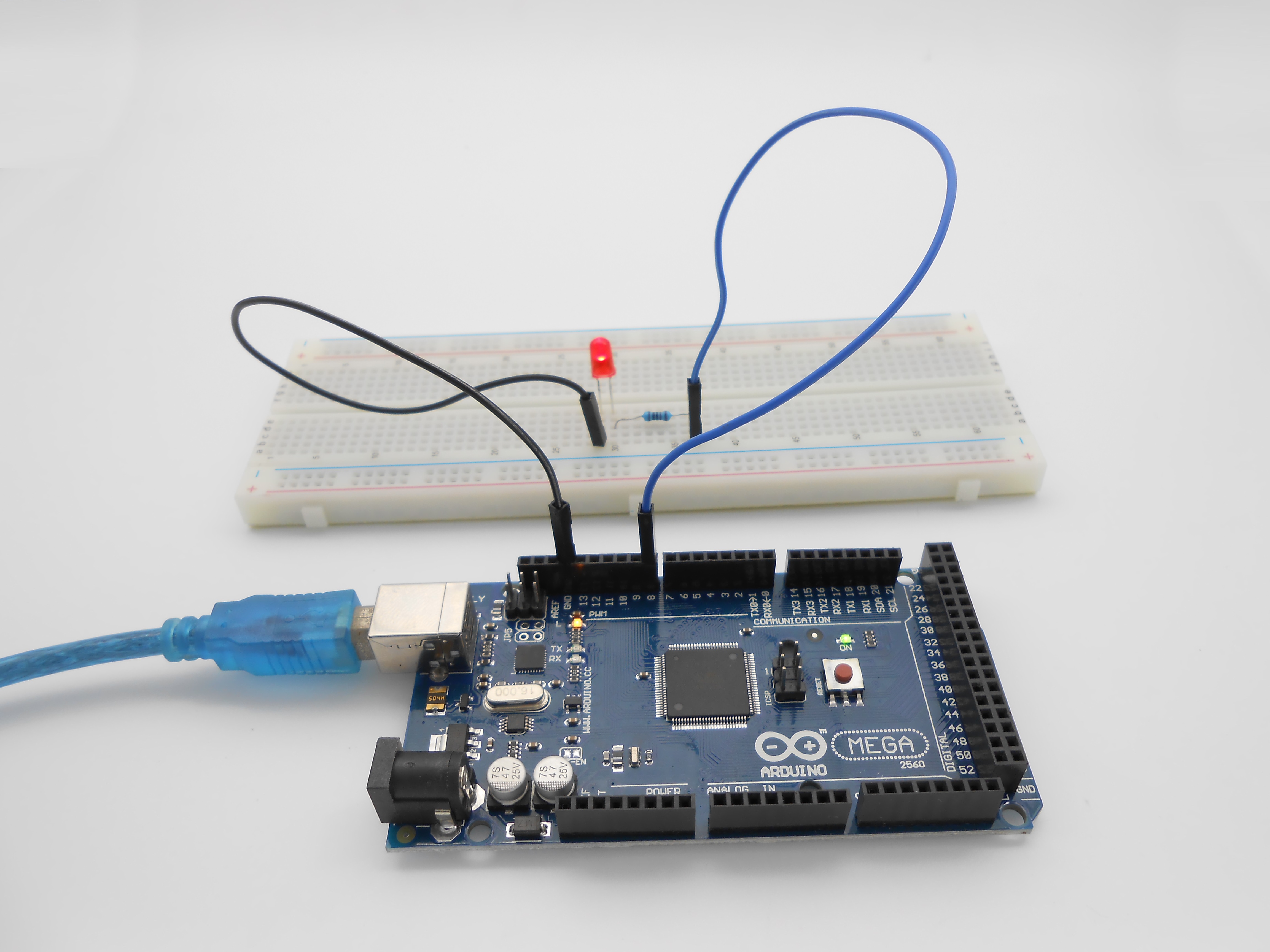
Procedures
1. Build the circuit
2. Program
/***********************************************************
File name:   01_blinkingLed.ino
Description:  Lit LED, let LED blinks.
Website: www.adeept.com
E-mail: support@adeept.com
Author: Tom
Date: 2015/12/27
***********************************************************/
int ledPin=8; //definition digital 8 pins as pin to control the LED
void setup()
{
    pinMode(ledPin,OUTPUT);    //Set the digital 8 port mode, OUTPUT: Output mode
}
void loop()
{
    digitalWrite(ledPin,HIGH); //HIGH is set to about 5V PIN8
    delay(1000);               //Set the delay time, 1000 = 1S
    digitalWrite(ledPin,LOW);  //LOW is set to about 5V PIN8
    delay(1000);               //Set the delay time, 1000 = 1S
}
3. Compile the program and upload to Arduino MEGA 2560 board
Now, you can see the LED is blinking.