Overview
In this lesson, we will learn how to program the Arduino to make an active buzzer sound.
Requirement
- 1* Arduino MEGA 2560
- 1* USB cable
- 1* Active buzzer
- 1* 1 kΩ Resistor
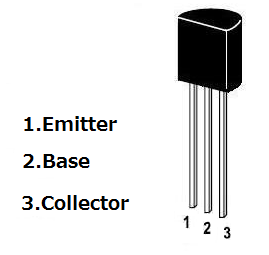
- 1* NPN Transistor (S8050)
- 1* Breadboard
- Several Jumper Wires
Principle
A buzzer or beeper is an audio signaling device. As a type of electronic buzzer with integrated structure, which use DC power supply, are widely used in computers, printers, photocopiers, alarms, electronic toys, automotive electronic equipments, telephones, timers and other electronic products for voice devices. Buzzers can be categorized as active and passive buzzers (See the following pictures).

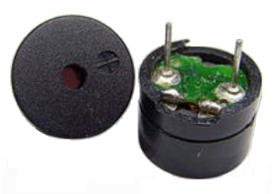
When you place the pins of buzzers upward, you can see that two buzzers are different, the buzzer that green circuit board exposed is the passive buzzer.
In this study, the buzzer we used is active buzzer. Active buzzer will sound as long as the power supply. We can program to make the Arduino output alternating high and low level, so that the buzzer sounds.
A slightly larger current is needed to make a buzzer sound. However, the output current of Arduino’s GPIO is weak, so we need a transistor to drive the buzzer.
The main function of transistor is blowing up the voltage or current. The transistor can also be used to control the circuit conduction or deadline. And the transistor is divided into two kinds, one kind is NPN, for instance, the S8050 we provided; another kind is PNP transistor such as the S8550 we provided. The transistor we used is as shown in below:
There are two driving circuit for the buzzer:
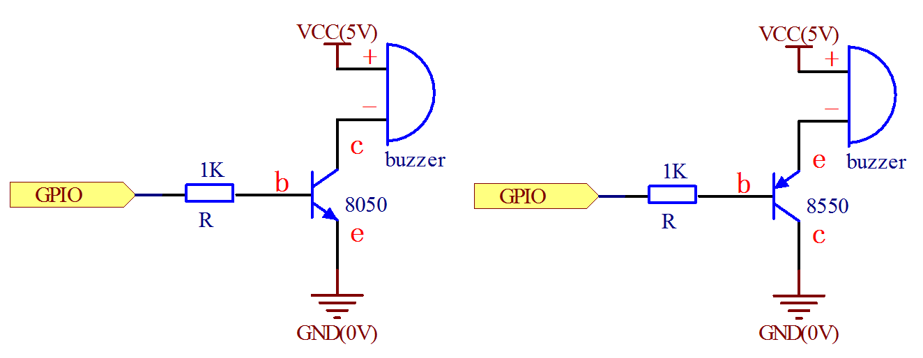
Figure1 Figure2
Figure 1: Set the Arduino GPIO as a high level, the transistor S8050 will conduct, and then the buzzer will sound; set the Arduino GPIO as low level, the transistor S8050 will cut off, then the buzzer will stop.
Figure 2: Set the Arduino GPIO as low level, the transistor S8550 will conduct, and the buzzer will sound; set the Arduino GPIO as a high level, the transistor S8550 will cut off, then the buzzer will stop.
Procedures
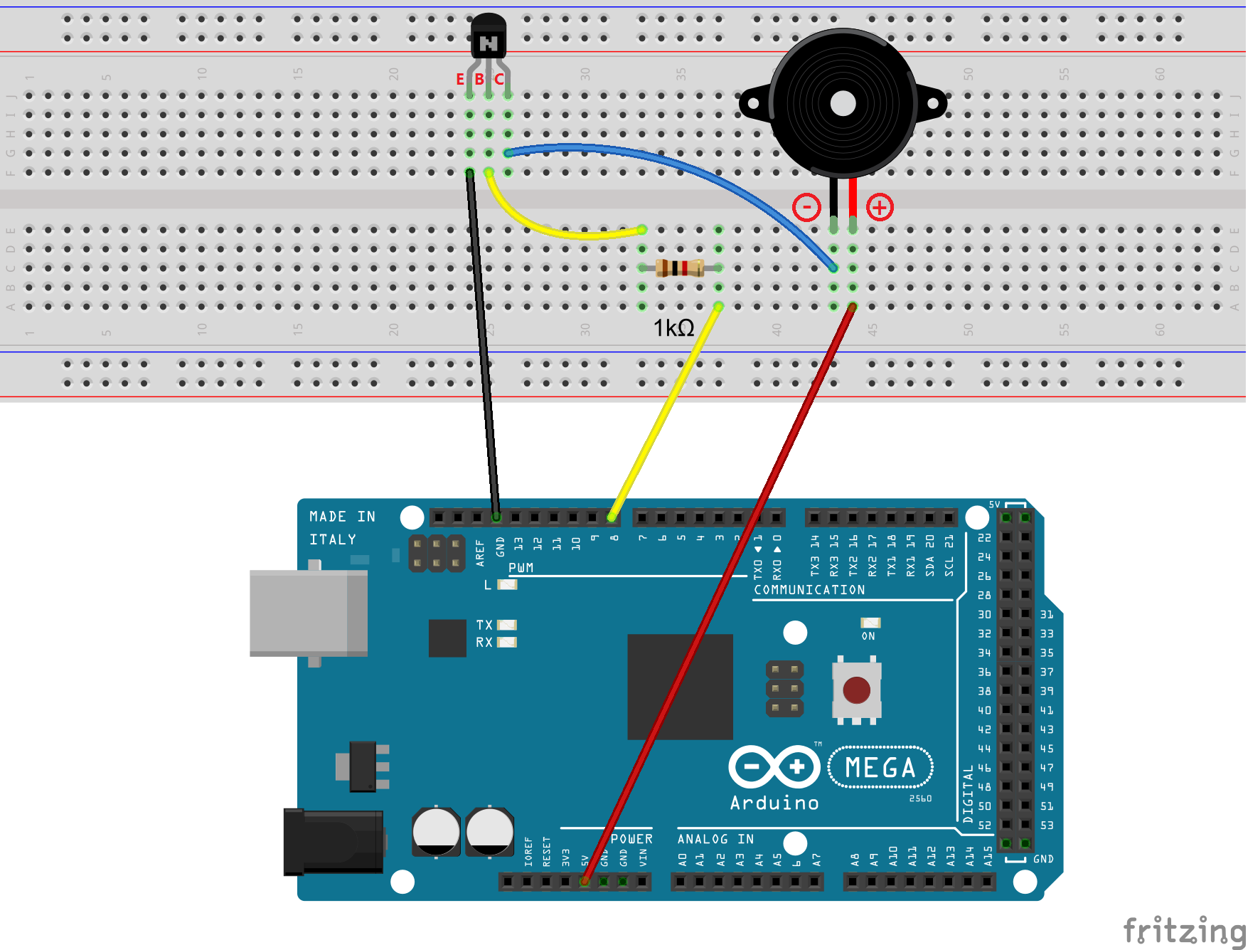
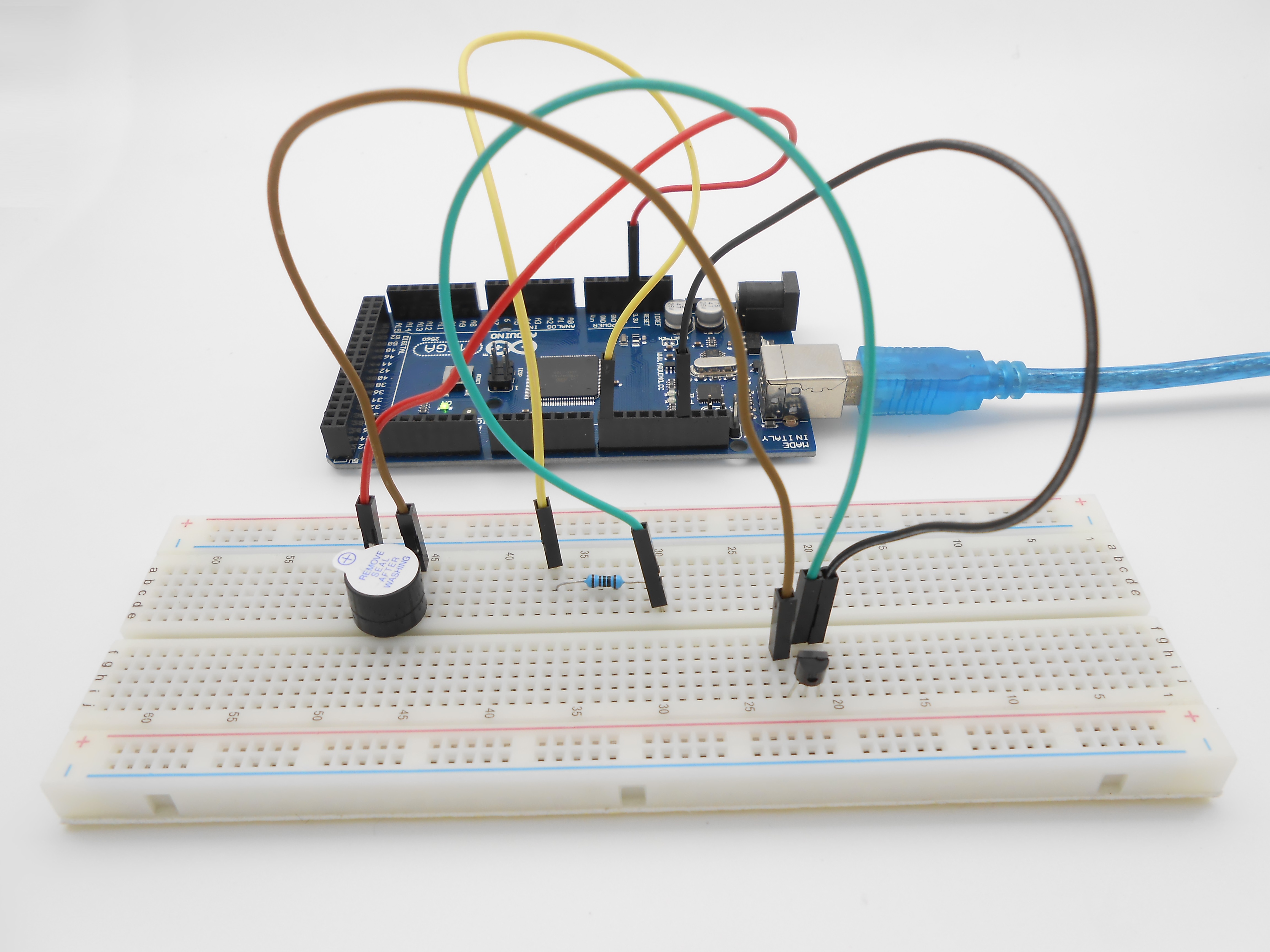
1. Build the circuit
2. Program
/***********************************************************
File name: 02_activeBuzzer.ino
Description: Arduino 2560 Continuous beeps control buzzer.
Website: www.adeept.com
E-mail: support@adeept.com
Author: Tom
Date: 2015/12/27
***********************************************************/
int buzzerPin=8; //definition digital 8 pins as pin to control the buzzer
void setup()
{
    pinMode(buzzerPin,OUTPUT); //Set digital 8 port mode, the OUTPUT for the output
}
void loop()
{
    digitalWrite(buzzerPin,HIGH); //Set PIN 8 feet as HIGH = 5 v
    delay(2000);                   //Set the delay time,2000ms
    digitalWrite(buzzerPin,LOW);  //Set PIN 8 feet for LOW = 0 v
    delay(2000);                   //Set the delay time,2000ms
}
3. Compile the program and upload to Arduino MEGA 2560 board
Now, you should be able to hear the sound of the buzzer.
Summary
By learning this lesson, we have mastered the basic principle of the buzzer and the transistor. We also learned how to program the Arduino and then control the buzzer. I hope you can use what you have learned in this lesson to do some interesting things.