Overview
In this lesson, we will program the Arduino for RGB LED control, and make RGB LED emits a various of colors of light.
Requirement
- 1* Arduino MEGA 2560
- 1* USB Cable
- 1* RGB LED
- 3* 220Ω Resistor
- 1* Breadboard
- Several Jumper Wires
Principle
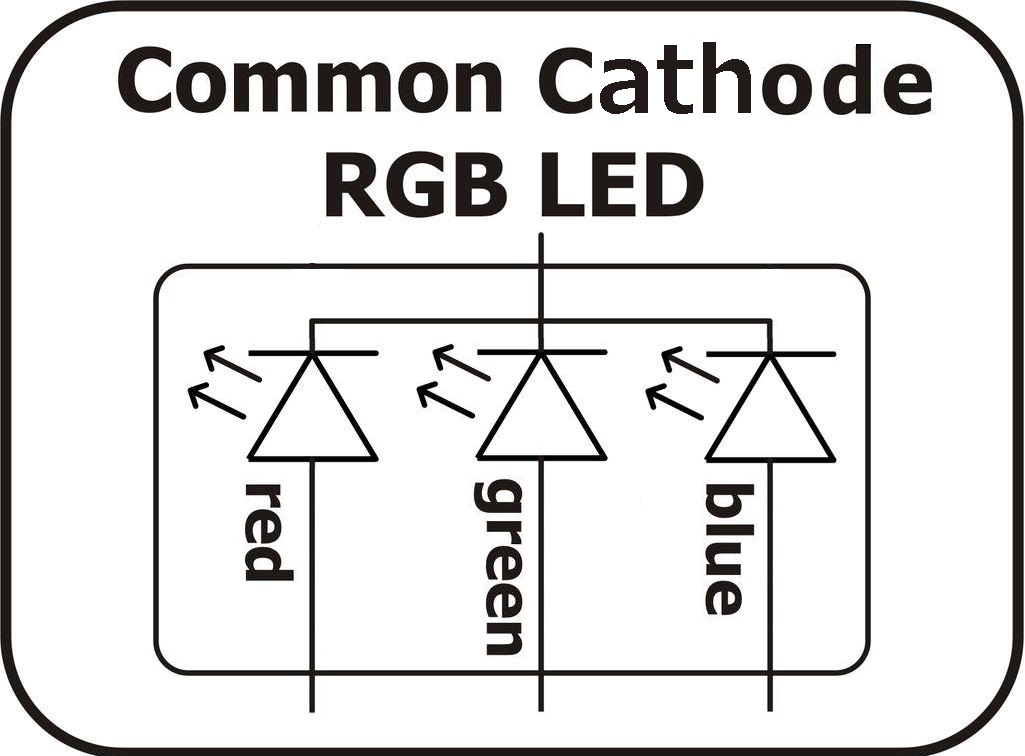
RGB LEDs consist of three LEDs. Each LED actually has one red, one green and one blue light. These three colored LEDs are capable of producing any color. Tri-color LEDs with red, green, and blue emitters, in general using a four-wire connection with one common lead (anode or cathode). These LEDs can have either common anode or common cathode leads.
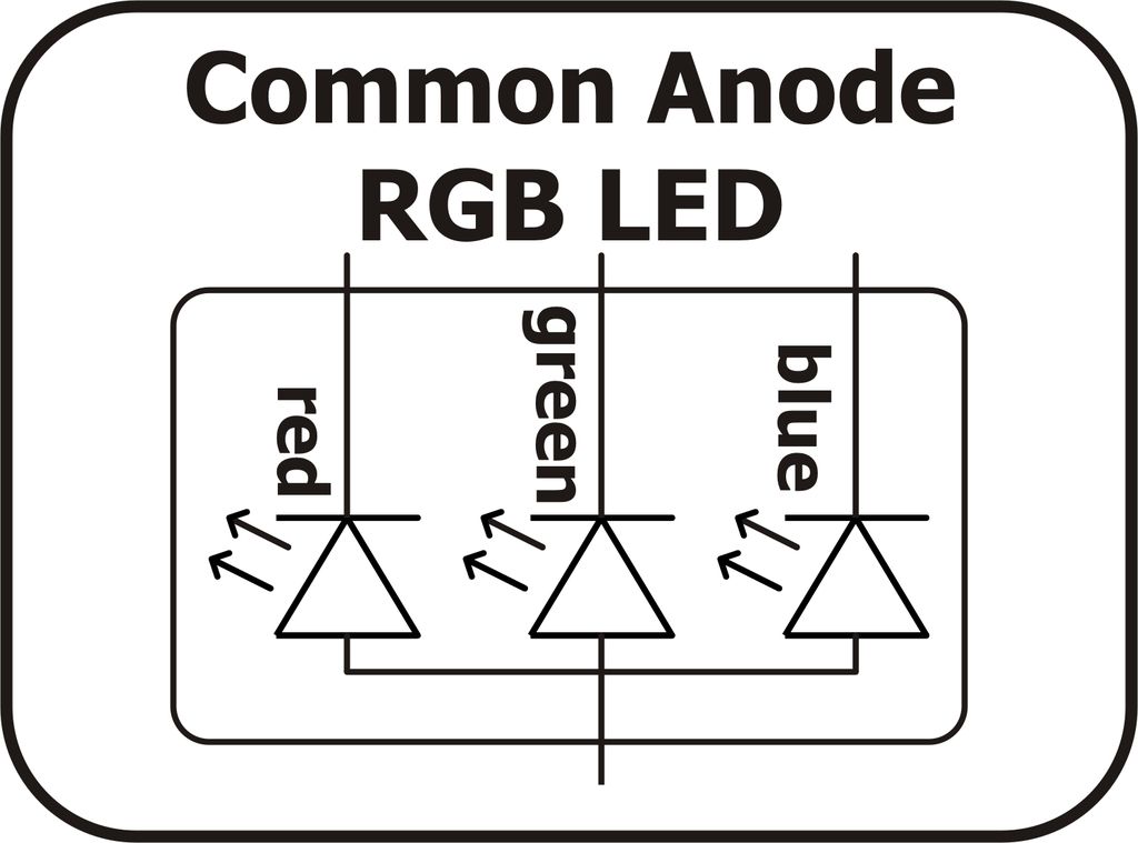
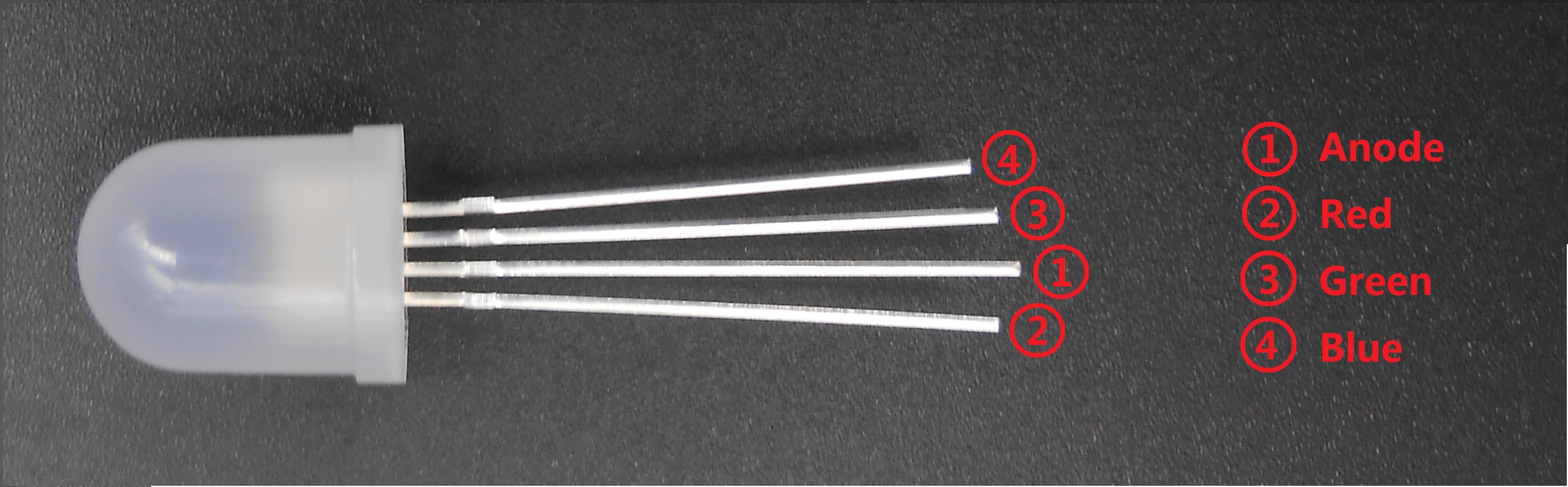
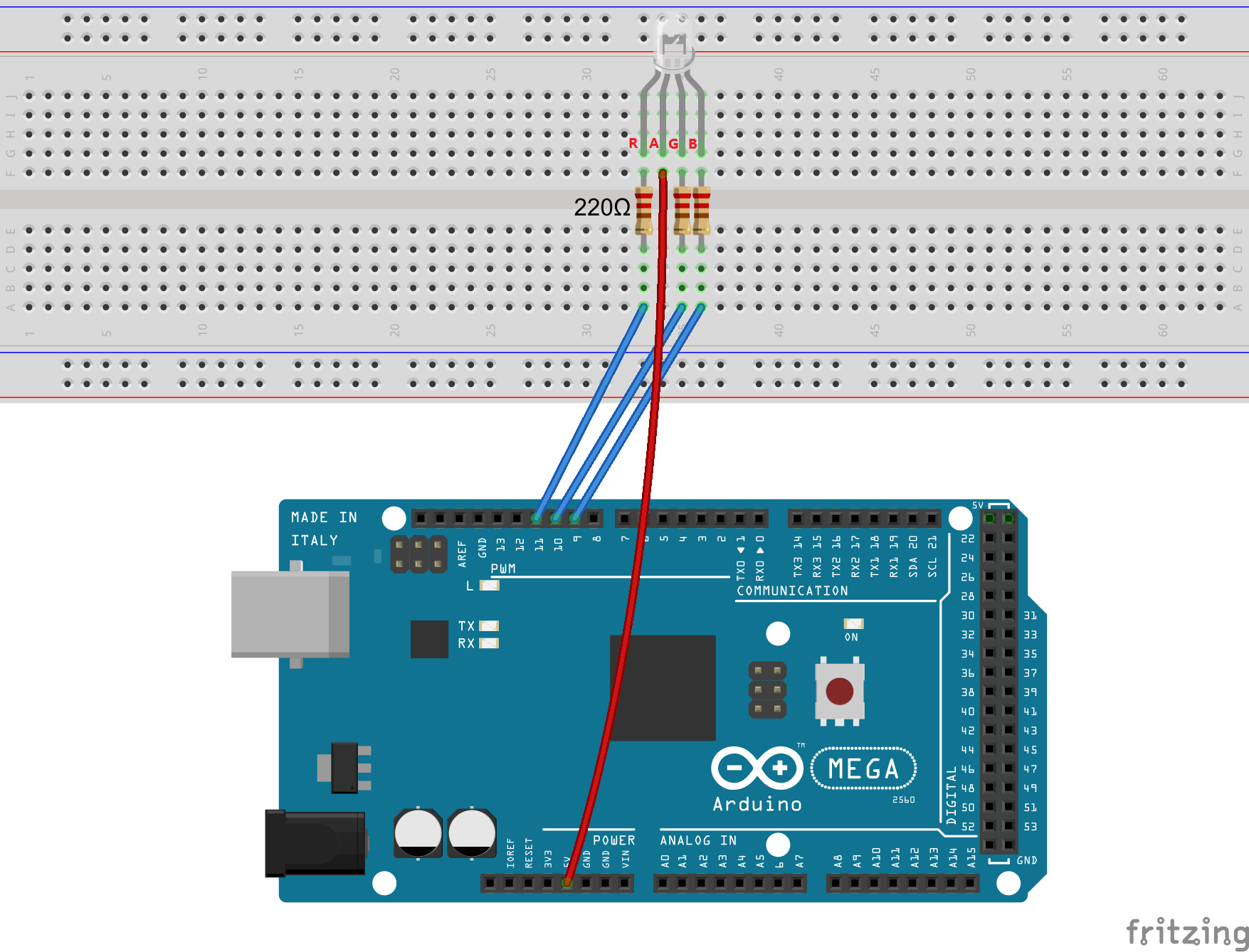
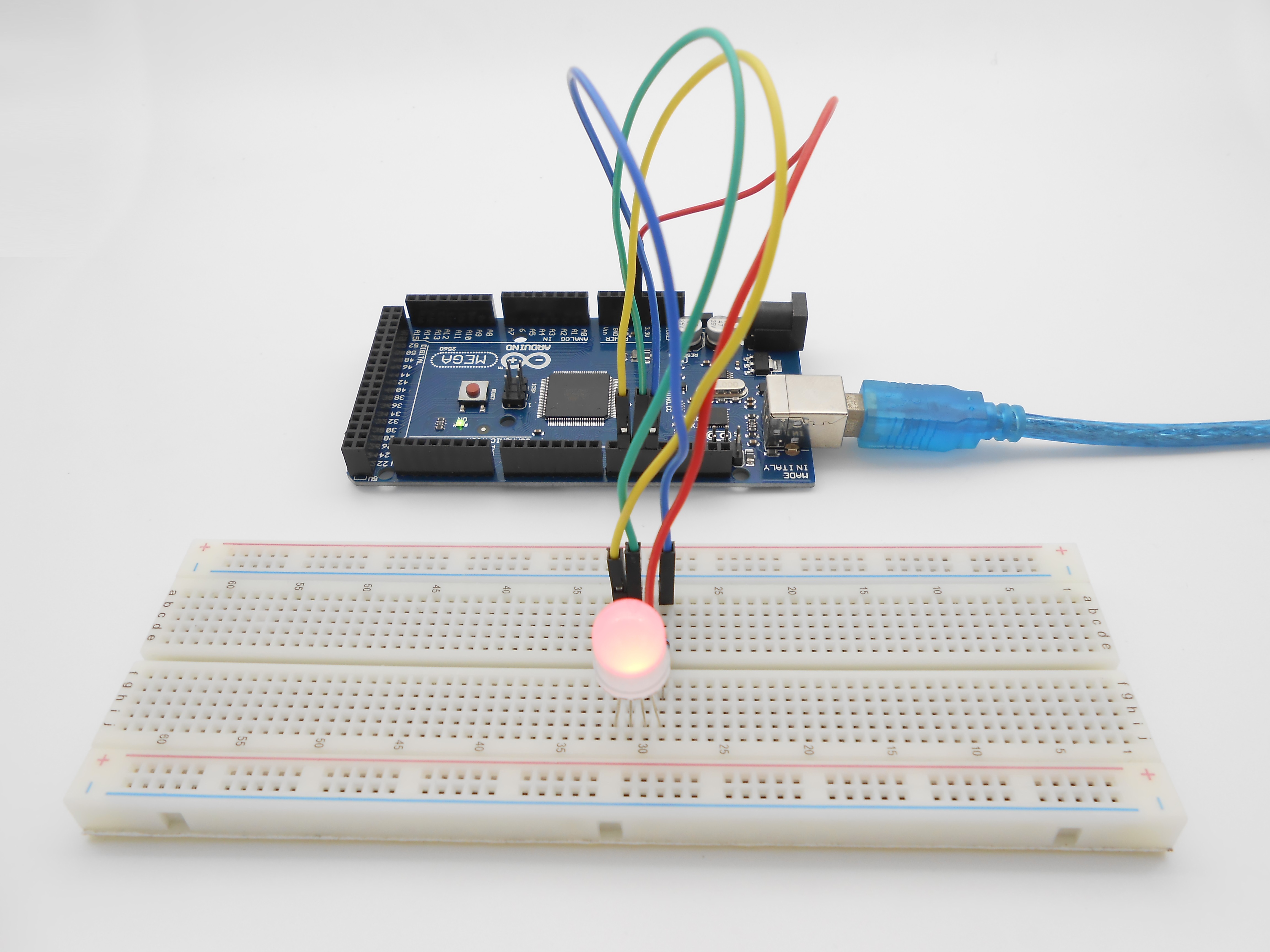
What we used in this experiment is the common anode RGB LED. The longest pin is the common anode of three LEDs. The pin is connected to the +5V pin of the Arduino, and the three remaining pins are connected to the Arduino’s D9, D10, D11 pins through a current limiting resistor.
In this way, we can control the color of RGB LED by 3-channel PWM signal.
Procedures
1. Build the circuit
2. Program
/***********************************************************
File name: 09_rgbLed.ino
Description:Control the RGB LED emitting red, green, blue, yellow,
            white and purple light, then the RGB LED will be off,
            each state continues 1s, after repeating the above
            procedure.
Website: www.adeept.com
E-mail: support@adeept.com
Author: Tom
Date: 2015/12/27
*************************************************************/
int redPin = 11;   // R petal on RGB LED module connected to digital pin 11
int greenPin = 10; // G petal on RGB LED module connected to digital pin 9
int bluePin = 9;   // B petal on RGB LED module connected to digital pin 10
void setup()
{
   pinMode(redPin, OUTPUT);   // sets the redPin to be an output
   pinMode(greenPin, OUTPUT); // sets the greenPin to be an output
   pinMode(bluePin, OUTPUT);  // sets the bluePin to be an output
}
void loop()  // run over and over again
{
    // Basic colors:
    color(255, 0, 0); // turn the RGB LED red
    delay(1000);      // delay for 1 second
    color(0,255, 0);  // turn the RGB LED green
    delay(1000);      // delay for 1 second
    color(0, 0, 255); // turn the RGB LED blue
    delay(1000);      // delay for 1 second

    // Example blended colors:
    color(255,255,0);   // turn the RGB LED yellow
    delay(1000);        // delay for 1 second
    color(255,255,255); // turn the RGB LED white
    delay(1000);        // delay for 1 second
    color(128,0,255);   // turn the RGB LED purple
     delay(1000);       // delay for 1 second
     color(0,0,0);      // turn the RGB LED off
     delay(1000);       // delay for 1 second
}

void color (unsigned char red, unsigned char green, unsigned char blue)// the color generating function
{
     analogWrite(redPin, 255-red);     // PWM signal output
     analogWrite(greenPin, 255-green); // PWM signal output
     analogWrite(bluePin, 255-blue);   // PWM signal output
}
3. Compile the program and upload to Arduino MEGA 2560 board
Now, you can see the RGB LED emitting red, green, blue, yellow, white and purple light, then the RGB LED will be off, each state continues 1s, after repeating the above procedure.
Summary
By learning this lesson, I believe you have already known the principle and the programming of RGB LED. I hope you can use your imagination to achieve even more cool ideas based on this lesson.