Overview
In this lesson, we will learn how to detect the state of a button, and then toggle the state of LED based on the state of the button.
Requirement
- 1* Arduino MEGA 2560
- 1* USB Cable
- 1* Button
- 1* LED
- 1* 10KΩ Resistor
- 1* 220Ω Resistor
- 1* Breadboard
- Several Jumper Wires
Principle
1. Button
Buttons are a common component used to control electronic devices. They are usually used as switches to connect or disconnect circuits. Although buttons come in a variety of sizes and shapes, the one used in this experiment will be a 12mm button as shown in the following pictures. Pins pointed out by the arrows of same color are meant to be connected.
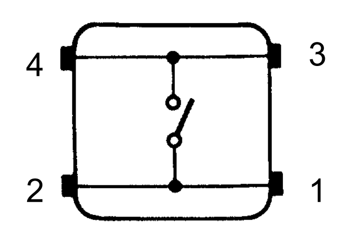
The button we used is a normally open type button. The two contacts of a button is in the off state under the normal conditions, only when the button is pressed they are closed.
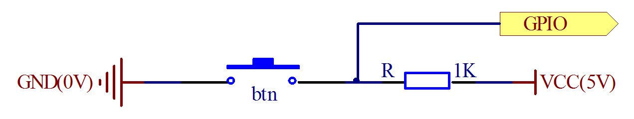
The schematic diagram we used is as follows:
The button jitter must be happen in the process of using. The jitter waveform is as the flowing picture:
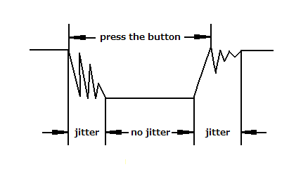
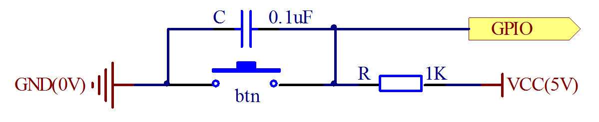
Each time you press the button, the Arduino will think you have pressed the button many times due to the jitter of the button. We must to deal with the jitter of buttons before we use the button. We can through the software programming method to remove the jitter of buttons, and you can use a capacitance to remove the jitter of buttons. We introduce the software method. First, we detect whether the level of button interface is low level or high level. When the level we detected is low level, 5~10 MS delay is needed, and then detect whether the level of button interface is low or high. If the signal is low, we can confirm that the button is pressed once. You can also use a 0.1 uF capacitance to clean up the jitter of buttons. The schematic diagram is shown in below:
2. interrupt
Hardware interrupts were introduced as a way to reduce wasting the processor's valuable time in polling loops, waiting for external events. They may be implemented in hardware as a distinct system with control lines, or they may be integrated into the memory subsystem.
3. Key functions:
●attachInterrupt(interrupt, ISR, mode)
Specifies a named Interrupt Service Routine (ISR) to call when an interrupt occurs. Replaces any previous function that was attached to the interrupt. Most Arduino boards have two external interrupts: numbers 0 (on digital pin 2) and 1 (on digital pin 3).
Generally, an ISR should be as short and fast as possible. If your sketch uses multiple ISRs, only one can run at a time, other interrupts will be ignored (turned off) until the current one is finished. as delay() and millis() both rely on interrupts, they will not work while an ISR is running. delayMicroseconds(), which does not rely on interrupts, will work as expected.
Syntax
attachInterrupt(pin, ISR, mode)
Parameters
pin: the pin number
ISR: the ISR will be called when the interrupt occurs; this function must take no parameters and return nothing. This function is sometimes referred to as an interrupt service routine.
mode: defines when the interrupt should be triggered. Four constants are predefined as valid values:
-LOW to trigger the interrupt whenever the pin is low,
-CHANGE to trigger the interrupt whenever the pin changes value
-RISING to trigger when the pin goes from low to high,
-FALLING for when the pin goes from high to low.
●digitalRead()
Reads the value from a specified digital pin, either HIGH or LOW.
Syntax
digitalRead(pin)
Parameters
pin: the number of the digital pin you want to read (int)
Returns
HIGH or LOW
●delayMicroseconds(us)
Pauses the program for the amount of time (in microseconds) specified as parameter. There are a thousand microseconds in a millisecond, and a million microseconds in a second.
Currently, the largest value that will produce an accurate delay is 16383. This could change in future Arduino releases. For delays longer than a few thousand microseconds, you should use delay() instead.
Syntax
delayMicroseconds(us)
Parameters
us: the number of microseconds to pause (unsigned int)
Returns
None
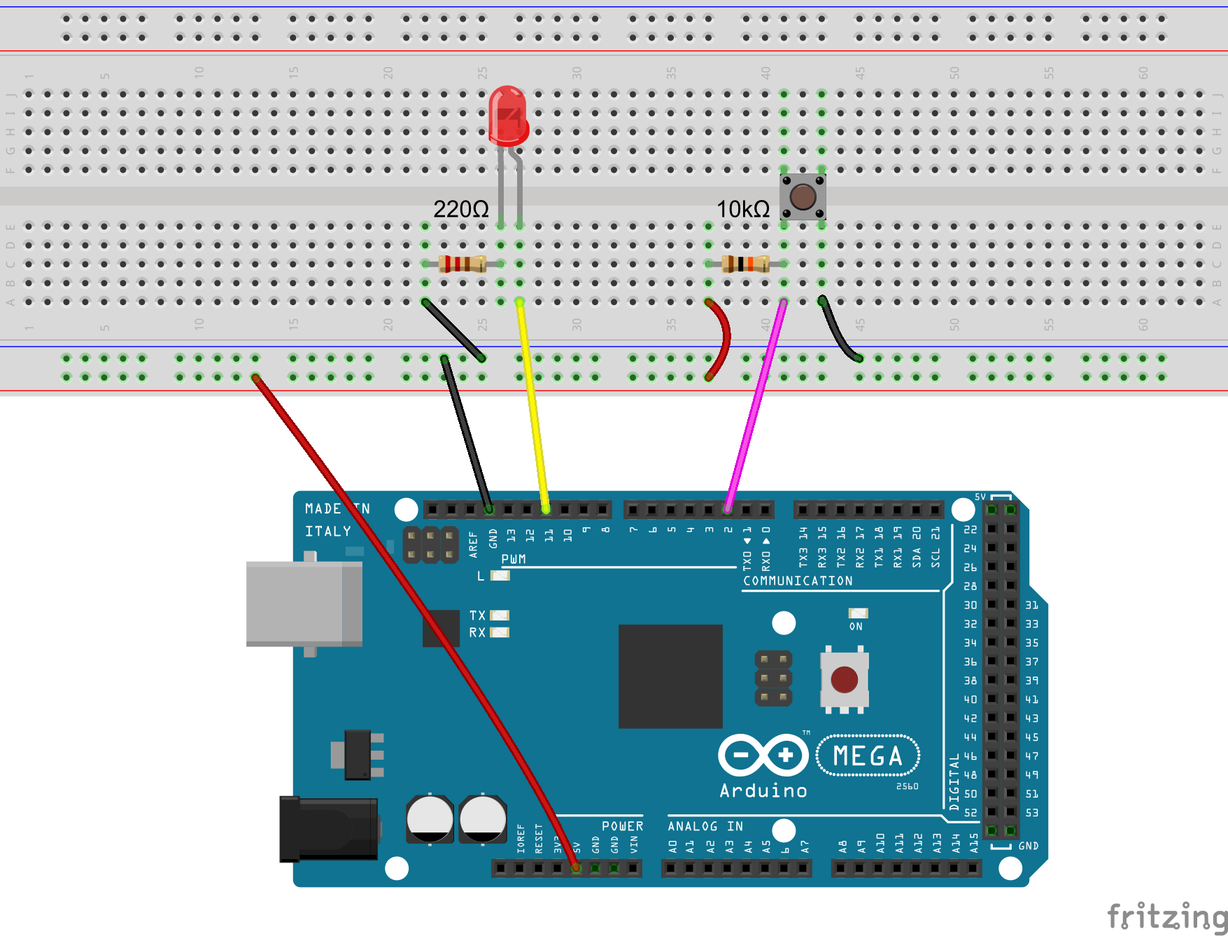
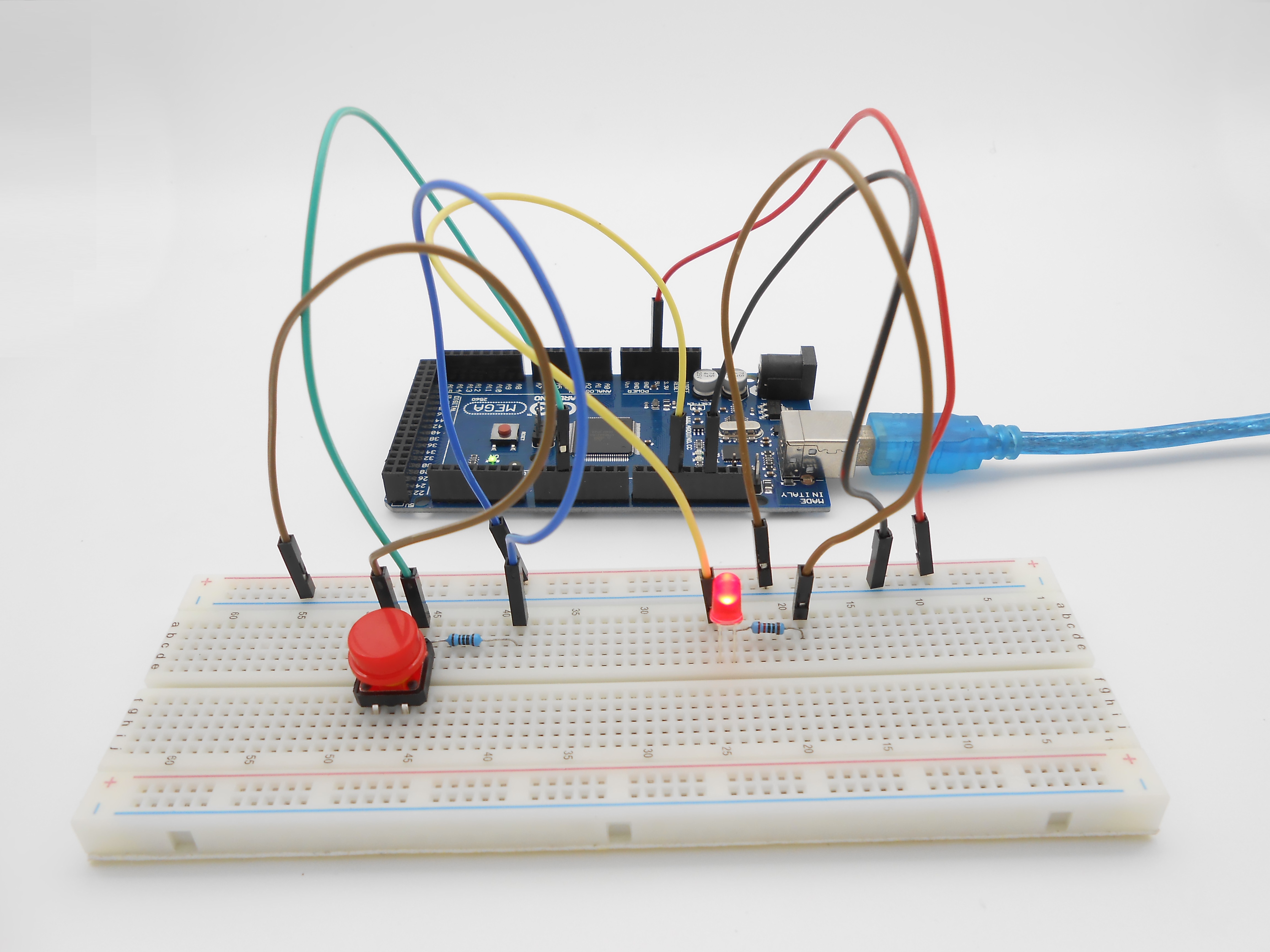
Procedures
1. Build the circuit
2. Program
/***********************************************************
File name: 03_btnAndLed01.ino
Description: When you press the button, you can see the state
              of the LED will be toggled. (ON->OFF,OFF->ON).
Website: www.adeept.com
E-mail: support@adeept.com
Author: Tom
Date: 2015/12/27
***********************************************************/

int ledpin=11;            //definition digital 11 pins as pin to control the LED
int btnpin=2;             //Set the digital 2 to button interface

volatile int state = LOW; // Defined output status LED Interface

void setup()
{
  pinMode(ledpin,OUTPUT);//Set digital 11 port mode, the OUTPUT for the output
  pinMode(btnpin,INPUT); //Set digital 2 port mode, the INPUT for the input
}

void loop()
{
  if(digitalRead(btnpin)==LOW)          //Detection button interface to low
  {
      delay(10);                        //Delay 10ms for the elimination of key leading-edge jitter
      if(digitalRead(btnpin)==LOW)      //Confirm button is pressed
      {
        while(digitalRead(btnpin)==LOW);//Wait for key interfaces to high
        delay(10);                      //delay 10ms for the elimination of key trailing-edge jitter
        while(digitalRead(btnpin)==LOW);//Confirm button release
        state = !state;                 //Negate operation, each time you run the program here, state the HGIH becomes LOW, or the state becomes the LOW HGIH.
        digitalWrite(ledpin,state);     //Output control status LED, ON or OFF
      }
   }
}
/***********************************************************
File name: 03_btnAndLed02.ino
Description: Using interrupt mode, every time you press the
button, LED status is switched(ON->OFF,OFF->ON).
Website: www.adeept.com
E-mail: support@adeept.com
Author: Tom
Date: 2015/12/27
***********************************************************/
int ledpin=11; //definition digital 11 pins as pin to control the LED
int btnpin=2; //Set the digital 2 to button interface
volatile int state = LOW; //Defined output status LED Interface
void setup()
{
pinMode(ledpin, OUTPUT); //Set digital 11 port mode, the OUTPUT for the output
attachInterrupt(0, stateChange, FALLING); //Monitoring Interrupt 0 (Digital PIN 2) changes in the input pins FALLING
}
void loop()
{
digitalWrite(ledpin, state); //Output control status LED, ON or OFF
}
void stateChange() //Interrupt function
{
if(digitalRead(btnpin)==LOW) //Detection button interface to low
{
delayMicroseconds(10000); //Delay 10ms for the elimination of key leading-edge jitter
if(digitalRead(btnpin)==LOW) //Confirm button is pressed
{
state = !state; //Negate operation, each time you run the program here, state the HGIH becomes LOW, or the state becomes the LOW HGIH.
}
}
}3. Compile the program and upload to Arduino MEGA 2560 board
When you press the button, you can see the state of the LED will be toggled. (ON->OFF,OFF->ON).
Summary
Through this lesson, you should have learned how to use the Arduino MEGA 2560 detects an external button state, and then toggle the state of LED relying on the state of the button detected before.