Overview
In this lesson, we will make a simple voltmeter with Arduino MEGA 2560 and LCD1602, the range of this voltmeter is 0~5V. Then, we will measure the voltage of the potentiometer’s adjustment end with the simple voltmeter and display it on the LCD1602.
Requirement
- 1* Arduino MEGA 2560
- 1* USB Cable
- 1* LCD1602
- 2* Potentiometer
- 1* Breadboard
- Several Jumper Wires
Principle
The basic principle of this experiment: Converting the analog voltage that the Arduino collected to digital quantity by the ADC(analog-to-digital converter) through programming, then display the voltage on the LCD1602.
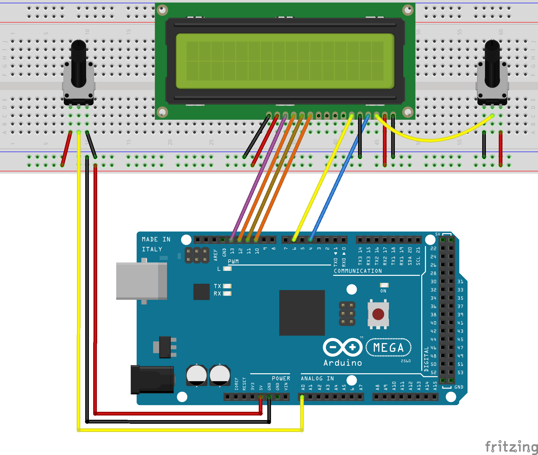
Connect the three wires from the potentiometer to your Arduino board. The first goes to ground from one of the outer pins of the potentiometer. The second goes from analog input 0 to the middle pin of the potentiometer. The third goes from 5 volts to the other outer pin of the potentiometer.
By turning the shaft of the potentiometer, you change the amount of resistance on either side of the wiper which is connected to the center pin of the potentiometer. This changes the voltage at the center pin. When the resistance between the center and the side connected to 5 volts is close to zero (and the resistance on the other side is close to 10 kilohms), the voltage at the center pin nears 5 volts. When the resistances are reversed, the voltage at the center pin nears 0 volts, or ground. This voltage is the analog voltage that you're reading as an input.
The Arduino has a circuit inside called an analog-to-digital converter that reads this changing voltage and converts it to a number between 0 and 1023. When the shaft is turned all the way in one direction, there are 0 volts going to the pin, and the input value is 0. When the shaft is turned all the way in the opposite direction, there are 5 volts going to the pin and the input value is 1023. In between, analogRead( ) returns a number between 0 and 1023 that is proportional to the amount of voltage being applied to the pin.
Key functions:
● analogRead()
Reads the value from the specified analog pin. The Arduino MEGA 2560 board contains a 16 channel (8 channels on the Mini and Nano, 6 on the UNO), 10-bit analog to digital converter. This means that it will map input voltages between 0 and 5 volts into integer values between 0 and 1023. This yields a resolution between readings of: 5 volts / 1024 units or, 0.0049 volts (4.9 mV) per unit. The input range and resolution can be changed using analogReference( ).
It takes about 100 microseconds (0.0001 s) to read an analog input, so the maximum reading rate is about 10,000 times a second.
Syntax
analogRead(pin)
Parameters
pin: the number of the analog input pin to read from (0 to 5 on most boards, 0 to 7 on the Mini and Nano, 0 to 15 on the Mega)
Returns
int (0 to 1023)
Procedures
1. Build the circuit
2. Program
/***********************************************************
File name: 12_voltage.ino
Description: Now, when you turning the shaft of the potentiometer,
             you will see the voltage displayed on the LCD1602
             will be changed.
Website: www.adeept.com
E-mail: support@adeept.com
Author: Tom
Date: 2015/12/27
***********************************************************/

#include <LiquidCrystal.h>

char array1[]="Adeept Voltmeter                  ";  //the string to print on the LCD
char array2[]=" Voltage: 0.00V                   ";  //the string to print on the LCD

// initialize the library with the numbers of the interface pins
LiquidCrystal lcd(4, 6, 10, 11, 12, 13);
int photoresistorPin = 0;  // potentiometer wiper (middle terminal) connected to analog pin 3
int val=0;
int tim = 50;              //the value of delay time

void setup()
{
  lcd.begin(16, 2);    // set up the LCD's number of columns and rows:
  lcd.clear();         //Clears the LCD screen and positions the cursor in the upper-left corner
  lcd.setCursor(0,0);  // set the cursor to column 15, line 0
  for (int positionCounter1 = 0; positionCounter1 < 16; positionCounter1++)
  {
      lcd.print(array1[positionCounter1]);  // Print a message to the LCD.
      delay(tim);      //wait for 250 microseconds
  }
}

void loop()
{
   val = analogRead(photoresistorPin)*(5.0 / 1023.0)*100;//Data collection
   array2[10]  = val/100%10+0x30;//Take one hundred - bit data
   array2[12] = val/10%10+0x30;  //Take ten-bit data
   array2[13] = val%10+0x30;     //Take a bit of data
   lcd.setCursor(0,1);           //Set the cursor to column 15, line 1
   for (int positionCounter3 = 0; positionCounter3 < 26; positionCounter3++)
   {
     lcd.print(array2[positionCounter3]);  // Print a message to the LCD.
     delay(tim);                 //Wait for 250 microseconds
   }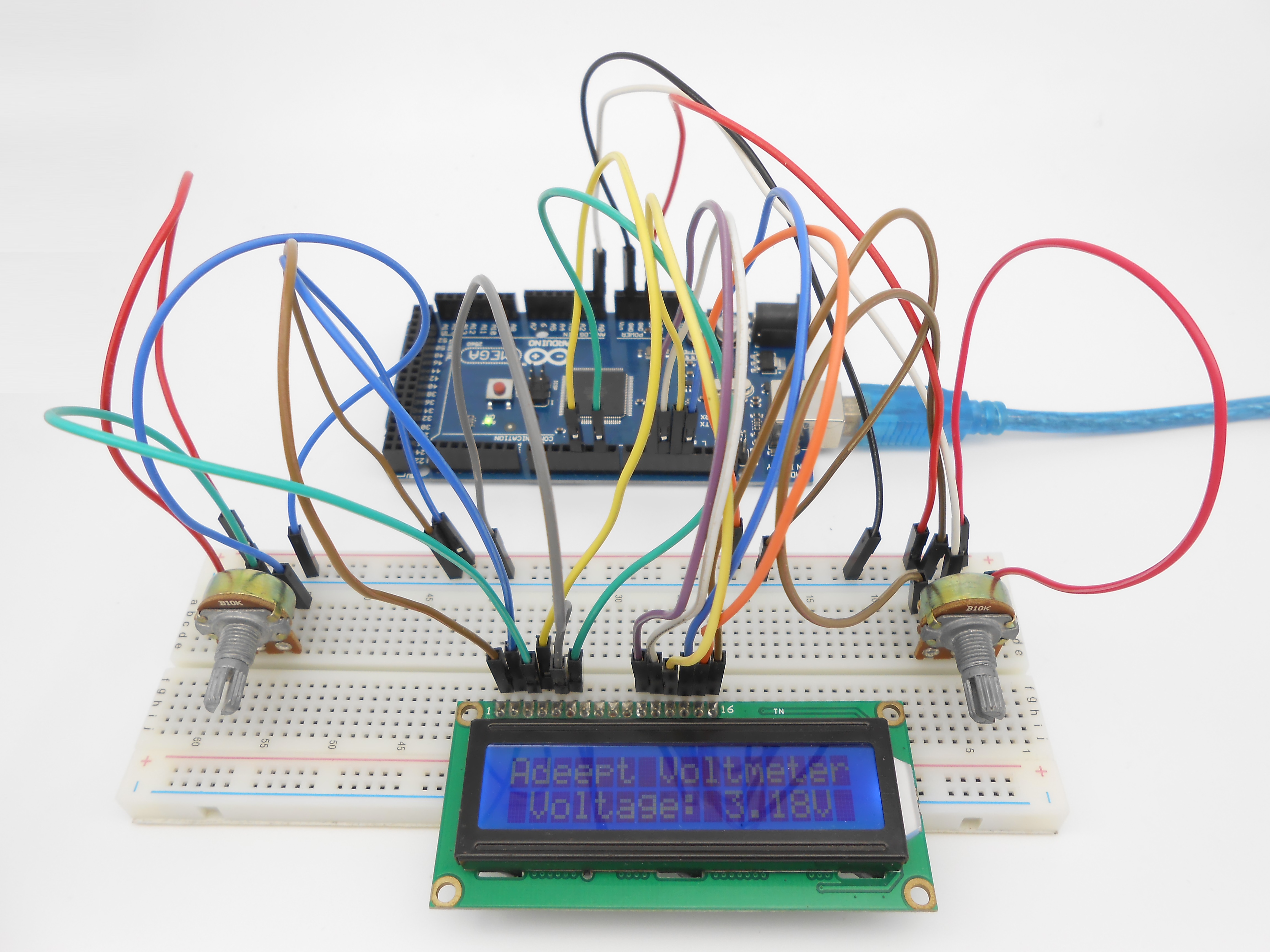
}3. Compile the program and upload to Arduino MEGA 2560 board.
Now, when you turning the shaft of the potentiometer, you will see the voltage displayed on the LCD1602 will be changed.
Summary
The substance of voltmeter is reading analog voltage which input to ADC inside. Through this course, I believe that you have mastered how to read analog value and how to make a simple voltmeter with Arduino.