In this lesson, we will carry out an interesting experiment to light up an LED with a Micro:bit.
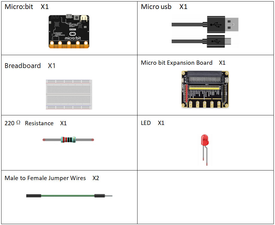
16.1 Components to be prepared
16.2 The LED Light-Emitting Diode
16.2.1 What is the Diode?
1. Definition:
A diode is an electronic device made of semiconductor materials (silicon, selenium, germanium, etc.). It has unidirectional conductivity. In the circuit, current (voltage) is allowed to flow in a single direction, and it will prevent current and voltage from passing in the opposite direction. Therefore, the diode has positive and negative poles (anode and cathode). When a positive voltage is applied to the anode and cathode of the diode, the diode conducts. When a reverse voltage is applied to the anode and cathode, the diode is turned off. Therefore, the turning on and off of the diode is equivalent to the turning on and off of the switch.
2. Structure of a diode:
A diode is made up of a PN junction plus corresponding electrode leads and package.
PN junction:
P-type semiconductor and N-type semiconductor are made on the same semiconductor (usually silicon or germanium) substrate, and a space charge region formed at their interface is called PN junction. The electrode drawn from the P area is called the anode, and the electrode drawn from the N area is called the cathode. Because of the unidirectional conductivity of the PN junction, the direction of the current when the diode is turned on is from the anode to the cathode through the inside of the tube. The following picture is a common diode:
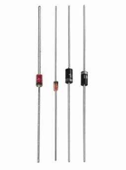
Picture 1-1
16.2.2 Anode (Positive Electrode) and Cathode (Negative Electrode) of Common Diodes:
1. The positive and negative electrodes of ordinary diodes are shown in the picture:
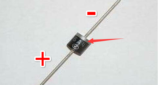
Picture 1-2
2. The positive and negative poles of the light-emitting diode are shown in the picture: the long pin is the positive pole, and the short pin is the negative pole.
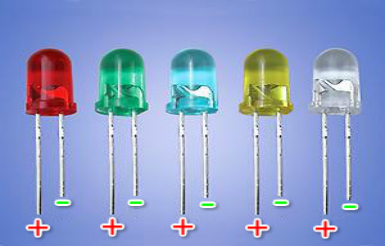
Picture 1-3
16.2.3 What is a Light-Emitting Diode?
1. Definition
Light-emitting diode is short as LED. The light-emitting diode is a type of diode, composed of a PN junction. With the characteristics of a diode, it has unidirectional conductivity like a diode. In the circuit, current can only flow in from the anode of the diode and out of the cathode. The difference between a light emitting diode and a diode is that it can emit light, red light, green light, blue light, yellow light, etc.
2. Why do LEDs emit light?
(1) The reason why the light-emitting diode emits light is that its core light-emitting part is a chip. The chip in the light-emitting diode is a compound gallium nitride, which has a property: it emits light when low current passes, mainly to convert electrical energy into light energy.
(2) The principle of light emitting diode:
The principle of light emission is mainly a combination of N (-: negative) semiconductors with many electrons (negatively charged) and P (+: positive) semiconductors with many holes (positively charged). When the semiconductor is applied with a forward voltage, electrons and holes will move and combine again at the junction. It is during the junction that a lot of energy is generated, and this energy is released in the form of light. As shown below:
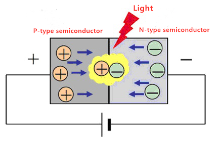
Picture 1-4
Light-emitting diodes have a wide range of uses in modern society, such as lighting, displays, medical devices, circuits and instruments as indicator lights.
(3) Classification of light-emitting diodes
Light-emitting diodes can also be divided into ordinary monochrome light-emitting diodes, high-brightness light-emitting diodes, ultra-high-brightness light-emitting diodes, color-changing light-emitting diodes, flashing light-emitting diodes, voltage-controlled light-emitting diodes, infrared light-emitting diodes, and negative resistance light-emitting diodes.
16.2.4 How to wire (connect) the LED in the circuit
1. The LED has positive and negative poles. When connecting to the circuit, we need to connect the positive pole of the LED to the positive pole of the power supply, and the negative pole to the negative pole of the power supply. The light emitting diode cannot be directly connected to the power supply, which can damage the components. In the circuit using LED light-emitting diodes, a resistor with a certain resistance value must be connected in series.
2. Calculation formula of LED current limiting resistor:

The limit current I of the LED light-emitting diode in our course is 5-20mA, and the limit voltage U is 3.3V, so our limit resistance R is:
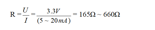
In the experiment, when we choose the connecting resistance, we can only choose between 165Ω ~ 660Ω.
3. The circuit diagram of the LED light-emitting diode is as follows:
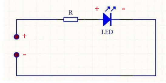
Picture 1-5
4.Two ways to connect LED and GPIO:
The first method is as shown in the picture below: The positive pole of the LED is connected to the positive pole of VCC (+ 3.3V), and the negative pole of the LED is connected to the Raspberry Pi GPIO. When GPIO outputs a low level, the LED lights up because of a potential difference between VCC and GPIO; when GPIO outputs a high level, because the potential difference between VCC and GPIO does not form, the LED turns off.

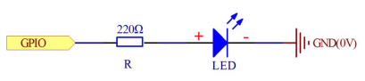
The second method is as follows: the positive pole of the LED is connected to GPIO, and the negative pole of the LED is connected to GND (0V). When the GPIO outputs a high level, the LED lights up because of the potential difference between GPIO and GND; when the GPIO outputs a low level, because the potential difference between the GPIO and GND does not form, the LED lights are off.
16.2.5 Main parameters and precautions of Light-emitting Diodes
(1) Allowable power consumption (Pm): Maximum value of the product of the forward DC voltage applied to both ends of the LED and the current flowing through it. If this value is exceeded, the LED will become hot or damaged.
(2) Maximum forward DC current (IFm): Maximum forward DC current allowed to be added. Exceeding this value can damage the diode.
(3) Maximum reverse voltage (VRm): Maximum reverse voltage allowed to be applied. Above this value, the light emitting diode may be damaged by breakdown.
(4) Working environment (topm): Ambient temperature range where the LED can work normally. Below or above this temperature range, the LED will not work properly and the efficiency will be greatly reduced.
【Remarks】
LED cannot be directly connected to the power supply, which can damage the components. In the circuit using LED light-emitting diodes, a resistor with a certain resistance value must be connected in series.
16.3 Low level and high level
In circuit, the form of binary (0 and 1) is presented as low level and high level.
Low level is generally equal to ground voltage (0V). High level is generally equal to the operating voltage of components.
The low level of Micro:bit is 0V and high level is 3.3V, as shown below. When IO port on Micro:bit outputs high level, low-power components can be directly driven,like LED.

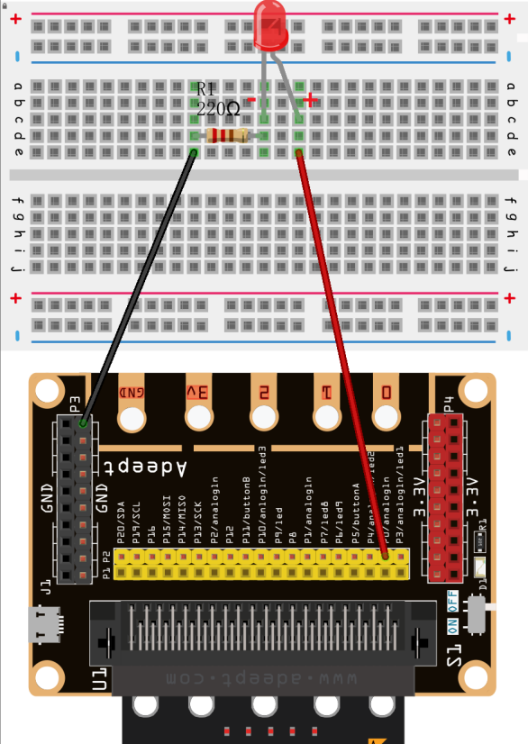
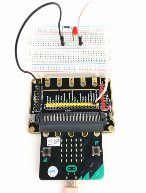
16.4 Circuit
You need to connect the components according to the circuit diagram below. The resistance used is 220Ω. Connect the positive and negative poles of the LED with the breadboard correctly.
16.5 MakeCode programming
Next, we will use the online MakeCode Editor to complete the experiment in this lesson.
16.5.1 Start programming
(1) Log in to the website
1. You need to enter the URL in the address bar of Google Browser:
https://makecode.microbit.org/
2. After the website is successfully opened, the interface as shown below will appear:

(2) Import a project
1. In the HOME interface, click the "Import" button to import the external ".hex" file:

In the pop-up dialog box, select the "Import File", as shown in the following figure:

Click the "Choose File"

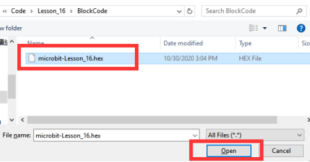
Find the code file for this lesson:
BBC _Microbit_Kit\Code\Lesson_16\BlockCode
Select the file in ".hex" format and click the Open:
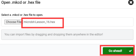
2. Notice whether the file has been loaded into the following window, and then click the "Go ahead!" button, as shown in the following figure:
3.You can see the following interface when successfully opening the file:
16.5.2 Run the program
1. After the program is written, connect micro:bit and PC with a Micro USB cable.
2. After micro:bit is connected to the computer, you need to first "Pair device". Click the  button on the right of
  in the lower left corner, and then click the
  option, as shown in the following figure:

Then click  in the lower right corner

Then the following dialog box will pop up, select  , and then click

After the device is successfully paired, the  button changes to

3. Start to download the program to Micro:bit, and click the  button. Generally, the program will be downloaded directly to the Micro:bit. After the download is completed, your Micro:bit will restart and run the program just downloaded.Observe whether the LED on the breadboard lights up, as shown in the following figure:
[Note]
If no experimental phenomenon has been detected after clicking the button  , you should click the button
  on the right of
  again, and click
  to observe Micro:bit for a second time, as shown below:

If you have problems, please send us an email: support@adeept.com
16.5.3 Learn the code program
The following instruction blocks will be applied in the program. Please see the description of the function as follows:
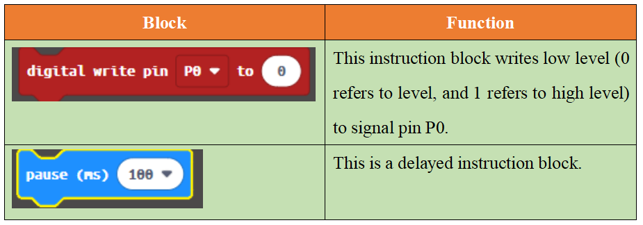
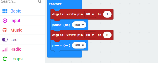
(1)In the code, write 1 to the P0 port to turn ON the LED. After waiting for 200ms, write 0 to the P0 port to turn OFF the LED.After waiting for 480ms, the LED will be turned ON again. Repeat the loop, then LED will start blinking.

16.6 Python programming
16.6.1 Run the program
1.Connect micro:bit and PC with a Micro USB cable.
2. Open the Mu Editor installed on the computer, and click the button [Load] in the upper left corner to open the source code program of this lesson:

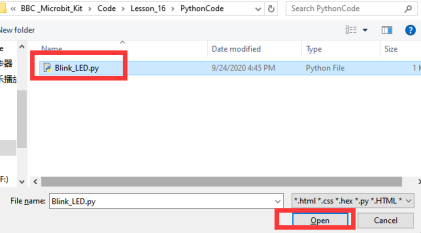
Find the code file for this lesson:
BBC _Microbit_Kit\Code\Lesson_16\PythonCode
Select the file in ".py" format and click the Open:
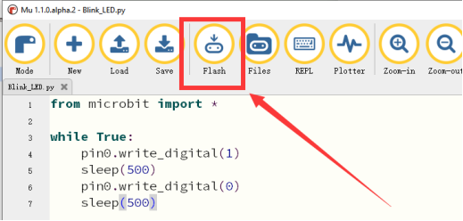
3. Click the [Flash] button to download the program to Micro:bit, as shown in the following figure:
4. After successfully downloading the program, when LED is on, it suggests that the experiment is a success.

If you have problems, please send us an email: support@adeept.com
16.6.2 Learn the code program
In the code, write 1 to the P0 port to turn ON the LED. After waiting for 500ms, write 0 to the P0 port to turn OFF the LED. After waiting for 500ms, the LED will be turned ON again. Repeat the loop, then LED will start blinking.
5 6 7 8 | pin0.write_digital(1) sleep(500) pin0.write_digital(0) sleep(500) |