In this lesson, we will carry out an interesting experiment by programming on the Micro:bit so as to read PS2 joystick data.
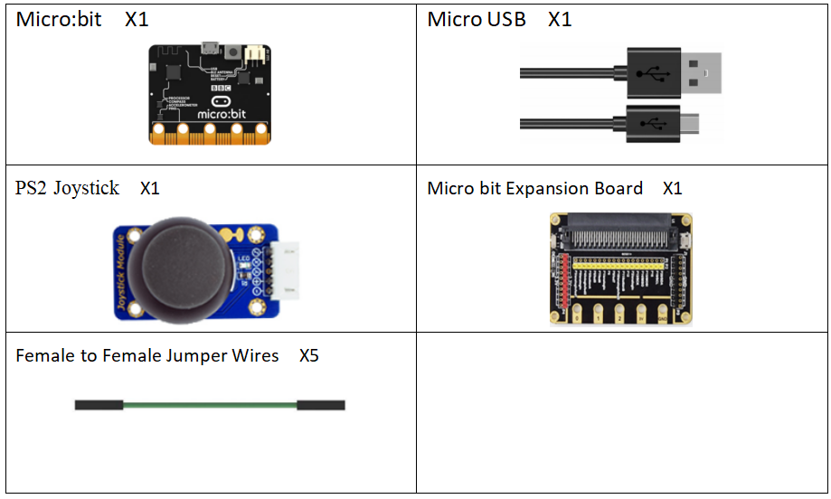
29.1 Components to be prepared
29.2 PS2 Joystick
29.2.1 PS2 Joystick
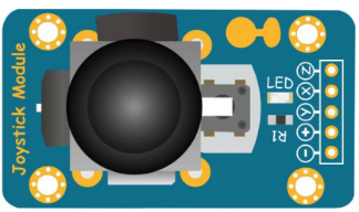
The PS2 joystick module is an input device consisting of a joystick that can rotate on the base and report its angle or direction to the device it controls. Joysticks are commonly used to control video games and robots. We use the joystick PS2. It consists of two sliding rheostats and a button.When the rocker is turned,the resistance of the sliding rheostat will change,and the corresponding X/Y voltage value will also change.If you press the rocker hard, the button will be triggered.When pressed,the corresponding SW signal will go low.
29.2.2 Working principle of the PS2 Joystick
The PS2 joystick module consists of two sliding rheostats and a button. When the joystick is turned, the resistance of the sliding rheostat changes, and the corresponding X/Y voltage value also changes. If you press the joystick, the button will be pressed and the corresponding SW signal goes low. This module uses 5V power supply. In the original state, the voltage read by X and Y is about 2.5V. When pressed in the direction of the arrow, the voltage value increases with the maximum value of 5V; when pressed in the opposite direction of the arrow, the voltage value is reduced to a minimum of 0V.
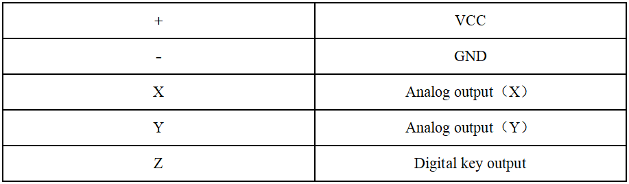
The PS2 joystick module has two analog outputs and one digital output interface. The output values correspond to the (X, Y) dual-axis offsets. The type is analog; the key indicates whether the user presses on the Z axis. It is a digital switch. The integrated power indicator of the module can display the working status; the coordinate identifier is clear, concise and accurate positioning. In order to more easily cooperate with standard interfaces such as expansion boards, the X and Y axis circuits are led separately in the design to control the input of the joystick module's X, Y values and to achieve a certain function under a specific value.
29.3 Low level and high level
In circuit, the form of binary (0 and 1) is presented as low level and high level.
Low level is generally equal to ground voltage (0V). High level is generally equal to the operating voltage of components.
The low level of Micro:bit is 0V and high level is 3.3V, as shown below. When IO port on Micro:bit outputs high level, low-power components can be directly driven,like LED.

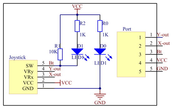
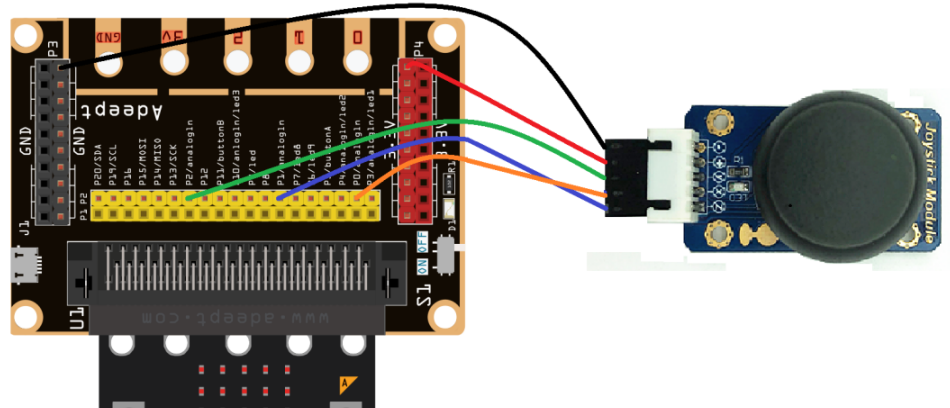
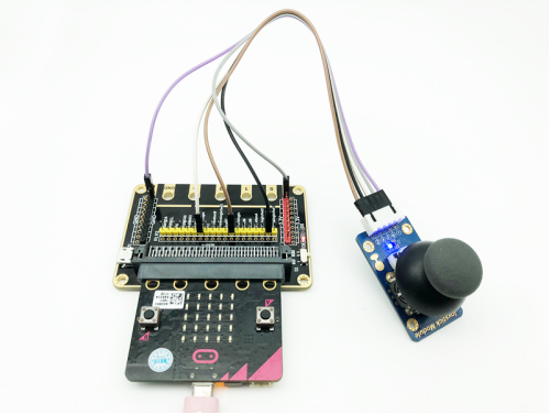
29.4 Circuit
You should connect the components according to the following circuit diagram, and view the pictures with the function “Zoom in”:
29.5 MakeCode programming
Next, we will use the online MakeCode Editor to complete the experiment in this lesson.
29.5.1 Start programming
(1) Log in to the website
1. You need to enter the URL in the address bar of Google Browser:
https://makecode.microbit.org/
2. After the website is successfully opened, the interface as shown below will appear:

(2) Import a project
1. In the HOME interface, click the "Import" button to import the external ".hex" file:

In the pop-up dialog box, select the "Import File", as shown in the following figure:

Click the "Choose File"

Find the code file for this lesson:
BBC_Microbit_Sensor\Code\Lesson_29\BlockCode
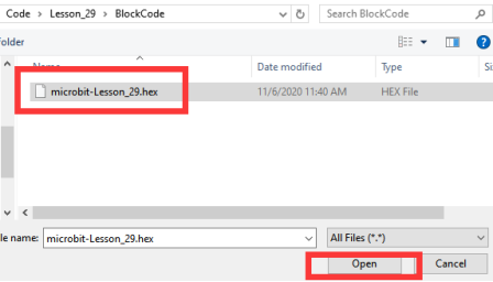
Select the file in ".hex" format and click the Open:
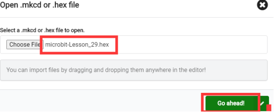
2. Notice whether the file has been loaded into the following window, and then click the "Go ahead!" button, as shown in the following figure:
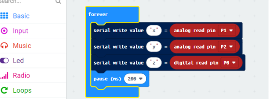
3.You can see the following interface when successfully opening the file:
29.5.2 Run the program
1. After the program is written, connect micro:bit and PC with a Micro USB cable.
2. After micro:bit is connected to the computer, you need to first "Pair device". Click the  button on the right of
  in the lower left corner, and then click the
  option, as shown in the following figure:

Then click  in the lower right corner

Then the following dialog box will pop up, select  , and then click

After the device is successfully paired, the  button changes to

3. Start to download the program to Micro:bit, and click the  button. Generally, the program will be downloaded directly to the Micro:bit. After the download is completed, your Micro:bit will restart and run the program just downloaded. Swing PS2 joystick, as shown below:

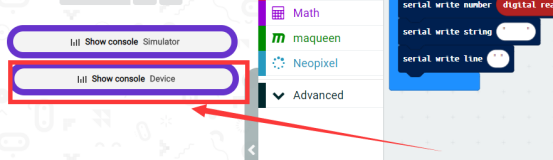
4.then click【Show console Device】:
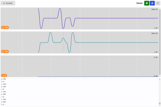
Then you will see the data on the X, Y, and Z axes of the PS2 joystick:
[Note]
1.If no experimental phenomenon has been detected after clicking the button  , you need to click the
  button on the right of the
  , and then click the
  ,observe the Micro:bit again, as shown in the following figure:

2. If no experimental phenomenon is observed, you should check whether the USB cable of Micro:bit is successfully connected. If not, please download the program again.
If you have problems, please send us an email: support@adeept.com
29.5.3 Learn the code program
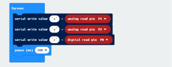
Read the X, Y and Z axis data of PS2 joystick cyclically, and print out the read data.
29.6 Python programming
29.6.1 Run the program
1.Connect micro:bit and PC with a Micro USB cable.
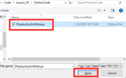
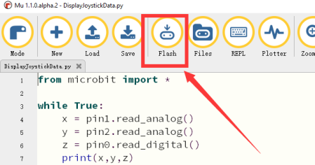
2. Open the Mu Editor installed on the computer, and click the button [Load] in the upper left corner to open the source code program of this lesson:

Find the code file for this lesson:
BBC_Microbit_Sensor\Code\Lesson_29\PythonCode
Select the file in ".py" format and click the Open:
3.Click button【Flash】to download the program to the Micro:bit. Click the button immediately (click the button ![]() when the Micro:bit indicator is flashing), and the output data will be read on the console, as shown below:
when the Micro:bit indicator is flashing), and the output data will be read on the console, as shown below:
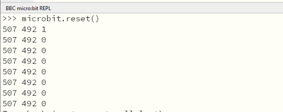
4.After downloading the program, swing the PS2 joystick, click the [REPL] button on the Mu Editor. In the console, you will see the data on the X, Y, and Z axes of the PS2 joystick:
【Note】
Click button【Flash】 to download the program again, if no data display on the console. Click the button  immediately (click the button
  when the Micro:bit indicator is flashing). Repeat the above steps or check whether the wiring is successfully connected, if no data are output, as shown below:
5.As shown below:
If you have problems, please send us an email: support@adeept.com
29.6.2 Learn the code program
Read the data of the X, Y, and Z axes of the PS2 joystick circularly, and print out the read data.\
3 4 5 6 7 8 | while True: x = pin1.read_analog() y = pin2.read_analog() z = pin0.read_digital() print(x,y,z) sleep(200) |