In this lesson, we will carry out an interesting experiment to make a breathing light with the Micro:bit.
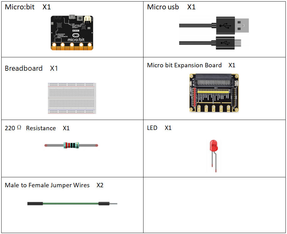
17.1 Components to be prepared
17.2 The working principle of the Breathing Light
17.2.1 What is a Breathing Light
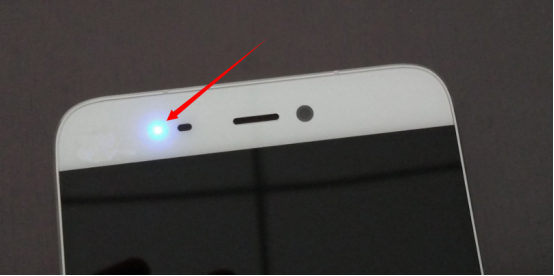
Breathing Light is a light that changes gradually from light to dark under the control of a microcomputer. It feels as if a person is breathing. It is widely used in mobile phones and has become one of the selling points of new mobile phones of major brands, serving as a notification and reminder.
17.2.2 The working principle of the breathing light
(1)The working principle of the breathing light
How does our breathing light achieve a similar lighting effect? The breath light controls the brightness of the LED by controlling the frequency (time) of the light flashing, and this process is repeated over and over again to create the effect of "breathing".
How to control the frequency (time) of LED flashing? It is through PWM (pulse width modulation) principle to achieve. We will introduce the principle of PWM as follow.
(2) Pulse width modulation (PWM)
1. Definition of pulse width modulation:
Pulse width modulation is an analog control method, which modulates the bias of the transistor base or MOS gate according to the change of the corresponding load to realize the change of the transistor or MOS tube conduction time, so as to realize the change of the output of the switching voltage stabilized power supply. This method can make the output voltage of the power supply remain constant when the working conditions change, and it is a very effective technique to control the analog circuit with the digital signal of the microprocessor. Pulse width modulation is a very effective technique for controlling analog circuits with the digital output of microprocessors. It is widely used in many fields, from measurement and communication to power control and transformation.
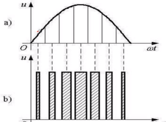
2. Principle of pulse width modulation
The control mode is to control the on-off of the inverter circuit switching device, so that the output end can get a series of pulses with the same amplitude, and use these pulses to replace the sine wave or the required waveform. In other words, multiple pulses are generated in the half period of the output waveform, so that the equivalent voltage of each pulse is a sinusoidal waveform, so that the output obtained is smooth and has fewer low-order harmonics. The width of each pulse can be modulated according to certain rules, which can not only change the output voltage of the inverter circuit, but also change the output frequency.
The above method may not be easy for you to understand, but you can understand it through the following sentence:
In the range of 0-1s: the lighting time of led lamp between 0-1ms is 0us; Light 1us in 1-2ms, light 2us in 2-3ms... Bright 999us in 999-1000ms.
3. Change duty cycle to realize breathing light:
The lighting and extinguishing of LED is the result of the level change, which can be regarded as a cycle. Each cycle will be shown as LED flicker. When the cycle is very short, that is, when the frequency is very high, this flicker will not be recognized by the naked eye, which will make people have the sense of continuous LED glow. In one cycle, the ratio between the duration of high level and the duration of one cycle is called duty cycle ratio. The higher the duty cycle is, the larger the current passing through the LED will be, and the brighter the visual perception will be. Now, you should have the train of thought that makes breathing light, namely change duty cycle! If the duty cycle is slightly stepped up, there will be a sense of brightening of LED. Otherwise it will get dark.
17.3 Low level and high level
In circuit, the form of binary (0 and 1) is presented as low level and high level.
Low level is generally equal to ground voltage (0V). High level is generally equal to the operating voltage of components.
The low level of Micro:bit is 0V and high level is 3.3V, as shown below. When IO port on Micro:bit outputs high level, low-power components can be directly driven,like LED.

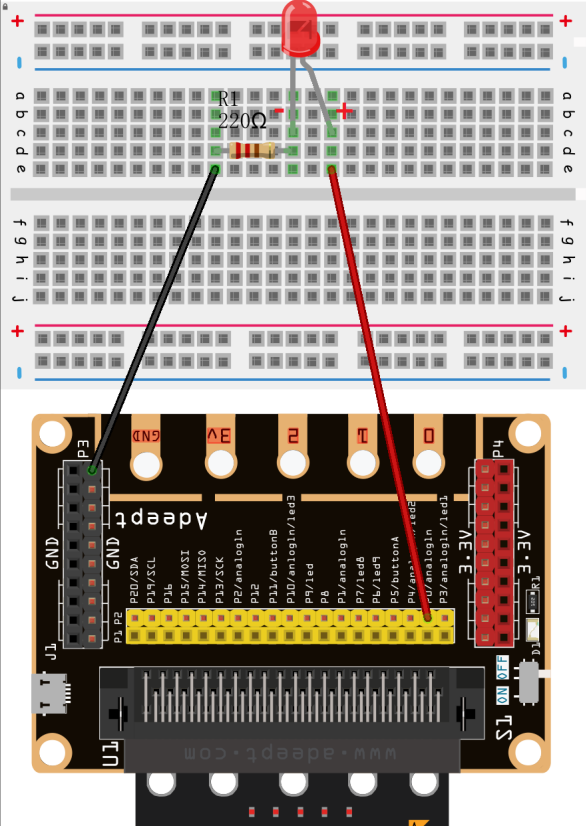
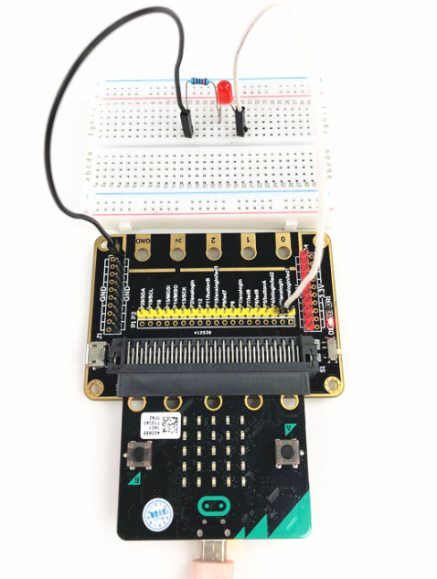
17.4 Circuit
You need to connect the components according to the circuit diagram below. The resistance used is 220Ω. Connect the positive and negative poles of the LED with the breadboard correctly.
17.5 MakeCode programming
Next, we will use the online MakeCode Editor to complete the experiment in this lesson.
17.5.1 Start programming
(1) Log in to the website
1. You need to enter the URL in the address bar of Google Browser:
https://makecode.microbit.org/
2. After the website is successfully opened, the interface as shown below will appear:

(2) Import a project
1. In the HOME interface, click the "Import" button to import the external ".hex" file:

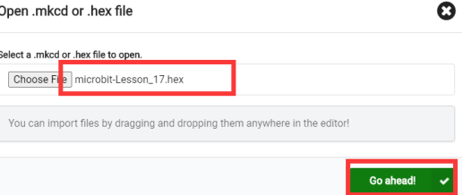
In the pop-up dialog box, select the "Import File", as shown in the following figure:

Click the "Choose File"

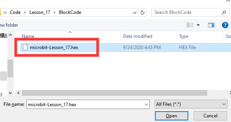
Find the code file for this lesson:
BBC _Microbit_Kit\Code\Lesson_17\BlockCode
Select the file in ".hex" format and click the Open:
2. Notice whether the file has been loaded into the following window, and then click the "Go ahead!" button, as shown in the following figure:
3.You can see the following interface when successfully opening the file:
17.5.2 Run the program
1. After the program is written, connect micro:bit and PC with a Micro USB cable.
2. After micro:bit is connected to the computer, you need to first "Pair device". Click the  button on the right of
  in the lower left corner, and then click the
  option, as shown in the following figure:

Then click  in the lower right corner

Then the following dialog box will pop up, select  , and then click

After the device is successfully paired, the  button changes to

3. Start to download the program to Micro:bit, and click the  button. Generally, the program will be downloaded directly to the Micro:bit. After the download is completed, your Micro:bit will restart and run the program just downloaded.Observe whether the LED on the breadboard changes gradually from light to dark, as shown in the following figure:
[Note]
If the LED on the breadboard doesn’t change gradually from light to dark after the  is clicked, you need to click the
  button on the right of the
  , then click the
  and observe the Micro:bit again, as shown in the following figure:

If you have problems, please send us an email: support@adeept.com
17.5.3 Learn the code program
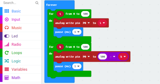
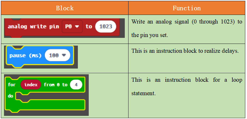
The following instruction blocks will be applied in the program. Please see the description of the function as follows:
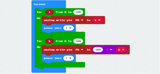
P0 outputs the PWM signal from 0 to 500, then from 500 to 0.
17.6 Python programming
17.6.1 Run the program
1.Connect micro:bit and PC with a Micro USB cable.
2. Open the Mu Editor installed on the computer, and click the button [Load] in the upper left corner to open the source code program of this lesson:

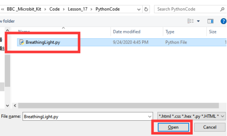
Find the code file for this lesson:
BBC _Microbit_Kit\Code\Lesson_17\PythonCode
Select the file in ".py" format and click the Open:
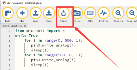
3. Click the [Flash] button to download the program to Micro:bit, as shown in the following figure:
4. After the program is downloaded, if the LED changes gradually from light to dark, it indicates the success of the experiment.
If you have problems, please send us an email: support@adeept.com
17.6.2 Learn the code program
P0 outputs PWM signal, from 0 to 500,sleep(1);Then from 500 to 0,sleep(1).
3 4 5 6 7 8 | for i in range(0, 500, 1): pin0.write_analog(i) sleep(1) for i in range(500, 0, -1): pin0.write_analog(i) sleep(1) |