In this lesson, we will conduct an interesting experiment to display numbers on a 7-segment digital tube by programming on Micro:bit.
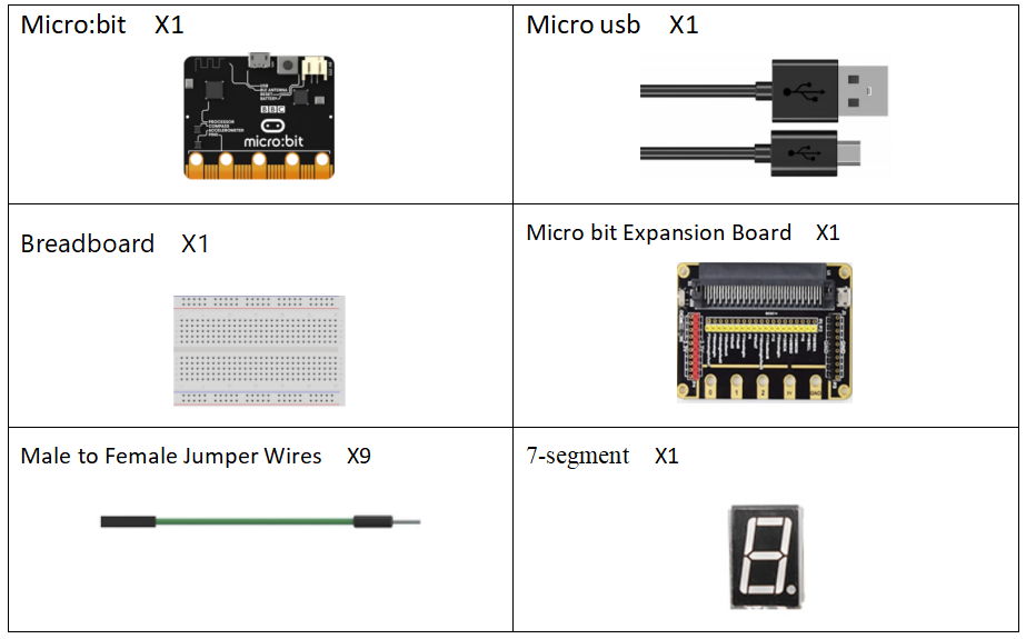
36.1 Components to be prepared
36.2 7-segment
36.2.1 7-segment
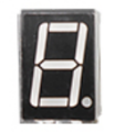
The 7-segment display is also called the 7-segment LED display. It is a type of LED display, using 7 LED lights to form the font "8", and another dot LED to display the decimal point, which means that there are 8 LED lights in total to form the font of "8."
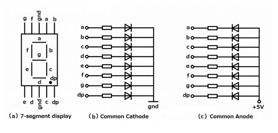
According to the connection form, it can be divided into common anode display and common cathode display. By controlling the display mode of semiconductor light emitting diodes, LED display panel (LED panel) is used to display information such as text, graphics, images, animations, quotes, videos, video signals, etc. The 7-segment display module is used to display numbers from decimal 0 to 9 and decimal point, and can also display English letters, including English A to F in hexadecimal (b and d are lowercase, others are uppercase).
36.2.2 Working principle of the 7-segment Display
The 7-segment display module is packaged by multiple LED light-emitting diodes. Each LED is called a segment. In addition to the seven-segment strokes necessary for displaying numbers, a decimal point is also provided in the display. It has 8 pins with numbers from a to g. By forward installing the appropriate pins of the LED segments in a specific order, some segments will be bright and others will be dark, allowing the desired character pattern of the numbers generated on the display. Then each of the ten decimal digits 0 to 9 can be displayed on the same 7-segment display.
The seven-segment display is an 8-shaped LED display device composed of eight LEDs (including a decimal point). The segments respectively named a, b, c, d, e, f, g, and dp.
The segment display can be divided into common anode and common cathode segment display by internal connections.
When using a common anode LED, the common anode should to be connected to the power supply (VCC); when using a common cathode LED, the common cathode should be connected to the ground (GND).
Each segment of a segment display is composed of LED, so a resistor is needed for protecting the LED.
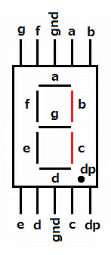
A 7-segment display has seven segments for displaying a figure andone more for displaying a decimal point. For example, if you want to display a number '1', you should only light the segment b and c, as shown below.
36.3 Low level and high level
In circuit, the form of binary (0 and 1) is presented as low level and high level.
Low level is generally equal to ground voltage (0V). High level is generally equal to the operating voltage of components.
The low level of Micro:bit is 0V and high level is 3.3V, as shown below. When IO port on Micro:bit outputs high level, low-power components can be directly driven,like LED.

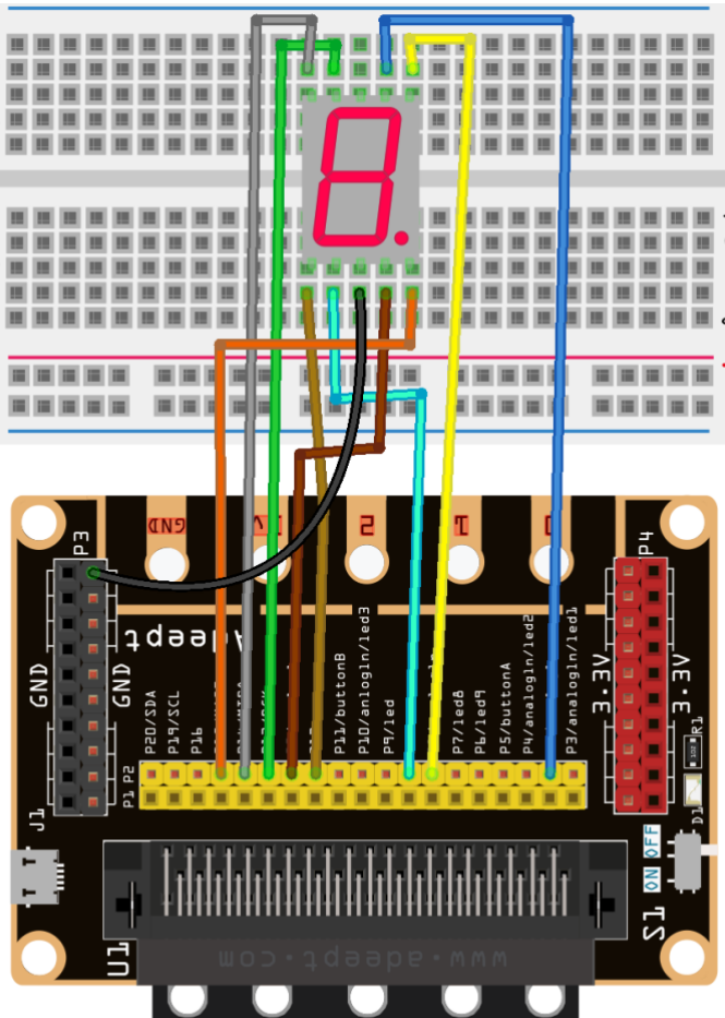
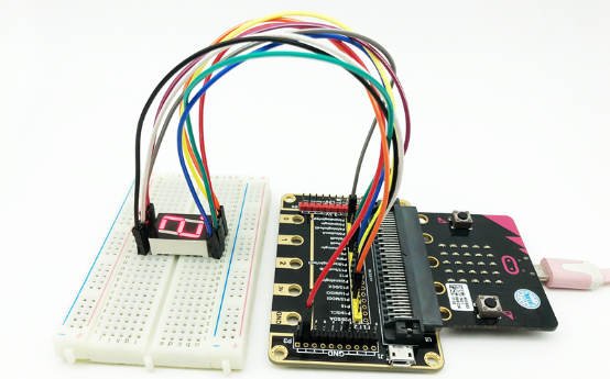
36.4 Circuit
You need to connect the components according to the following circuit diagram. You can use the “enlarge” function to view the picture.
36.5 MakeCode programming
Next, we will use the online MakeCode Editor to complete the experiment in this lesson.
36.5.1 Start programming
(1) Log in to the website
1. You need to enter the URL in the address bar of Google Browser:
https://makecode.microbit.org/
2. After the website is successfully opened, the interface as shown below will appear:

(2) Import a project
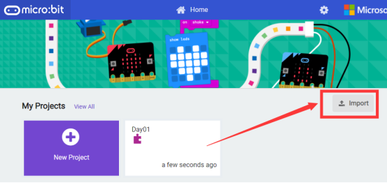
1. In the HOME interface, click the "Import" button to import the external ".hex" file:
In the pop-up dialog box, select the "Import File", as shown in the following figure:![]()

Click the "Choose File"

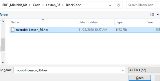
Find the code file for this lesson:
BBC _Microbit_Kit\Code\Lesson_36\BlockCode
Select the file in ".hex" format and click the Open:
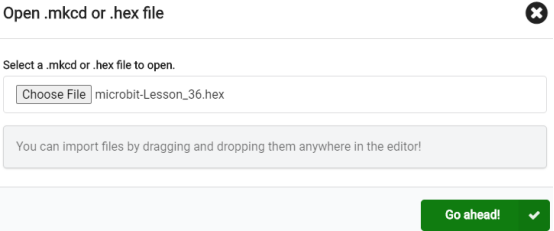
2. Notice whether the file has been loaded into the following window, and then click the "Go ahead!" button, as shown in the following figure:
3.You can see the following interface when successfully opening the file:
36.5.2 Run the program
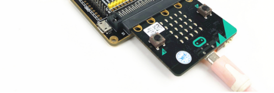
1. After the program is written, connect micro:bit and PC with a Micro USB cable.
2. After micro:bit is connected to the computer, you need to first "Pair device". Click the  button on the right of
  in the lower left corner, and then click the
  option, as shown in the following figure:

Then click  in the lower right corner

Then the following dialog box will pop up, select  , and then click

After the device is successfully paired, the  button changes to

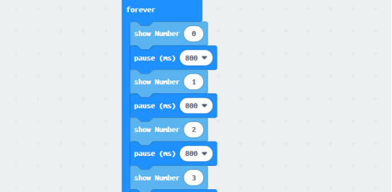
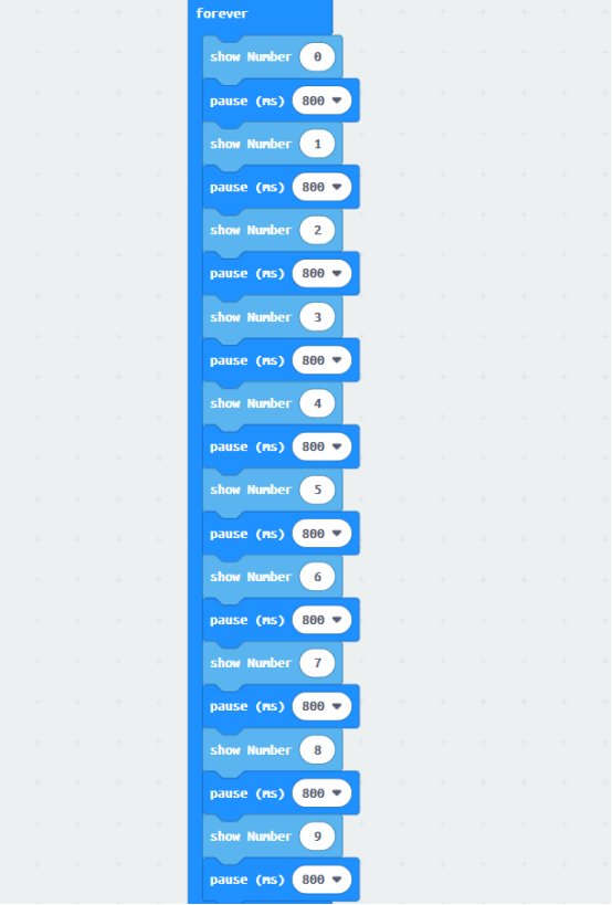
3. Start to download the program to Micro:bit, and click the  button. Generally, the program will be downloaded directly to the Micro:bit. After the download is completed, your Micro:bit will restart and run the program just downloaded.Observe The 7-segment on the breadboard will display 0~9, as shown below:

[Note]
1.If the active buzzer doesn’t sound after the  is clicked, you need to click the
  button on the right of the
  , then click the
  and observe the Micro:bit again, as shown in the following figure:

2.If the active buzzer still doesn’t sound, you need to unplug and then plug in the USB cable connected to the Micro:bit, and then download the program again.
If you have problems, please send us an email: support@adeept.com
36.5.3 Learn the code program
In the program, we used the following instruction block, and its function is explained as follows:
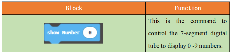
The numbers 0~9 are displayed on the 7-segment.
36.6 Python programming
36.6.1 Run the program
1.Connect micro:bit and PC with a Micro USB cable.
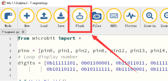
2. Open the Mu Editor installed on the computer, and click the button [Load] in the upper left corner to open the source code program of this lesson:

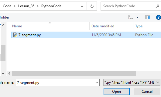
Find the code file for this lesson:
BBC _Microbit_Kit\Code\Lesson_36\PythonCode
Select the file in ".py" format and click the Open:
3. Click the [Flash] button to download the program to Micro:bit, as shown in the following figure:
4.After successfully downloading the program, observe that the 7-segment on the breadboard will display 0~9, as shown below:
If you have problems, please send us an email: support@adeept.com
36.6.2 Learn the code program
The following is an explanation of the course code in this section.
(1)Define the pins 0,1,2,8,12,13,14,15 connected to the Micro bit Expansion Board.
3 | pins = [pin0, pin1, pin2, pin8, pin12, pin13, pin14, pin15] |
(2)Define the numbers 0~9 that need to be displayed and output, expressed in octal.
5 6 | digits = [0b11111101, 0b01100001, 0b11011011, 0b11110011, 0b01100111, 0b10110111, 0b10111111, 0b11100001, 0b11111111, 0b11110111] |
(3)Output numbers 0~9.
8 9 10 11 | def WriteDigit(d): bits = [digits[d] >> i & 1 for i in range(7, -1, -1)] for p in range(0, 8): pins[p].write_digital(bits[p]) |