In this lesson, we will carry out an interesting experiment to use a Tilt Switch to control an LED with a Micro:bit.
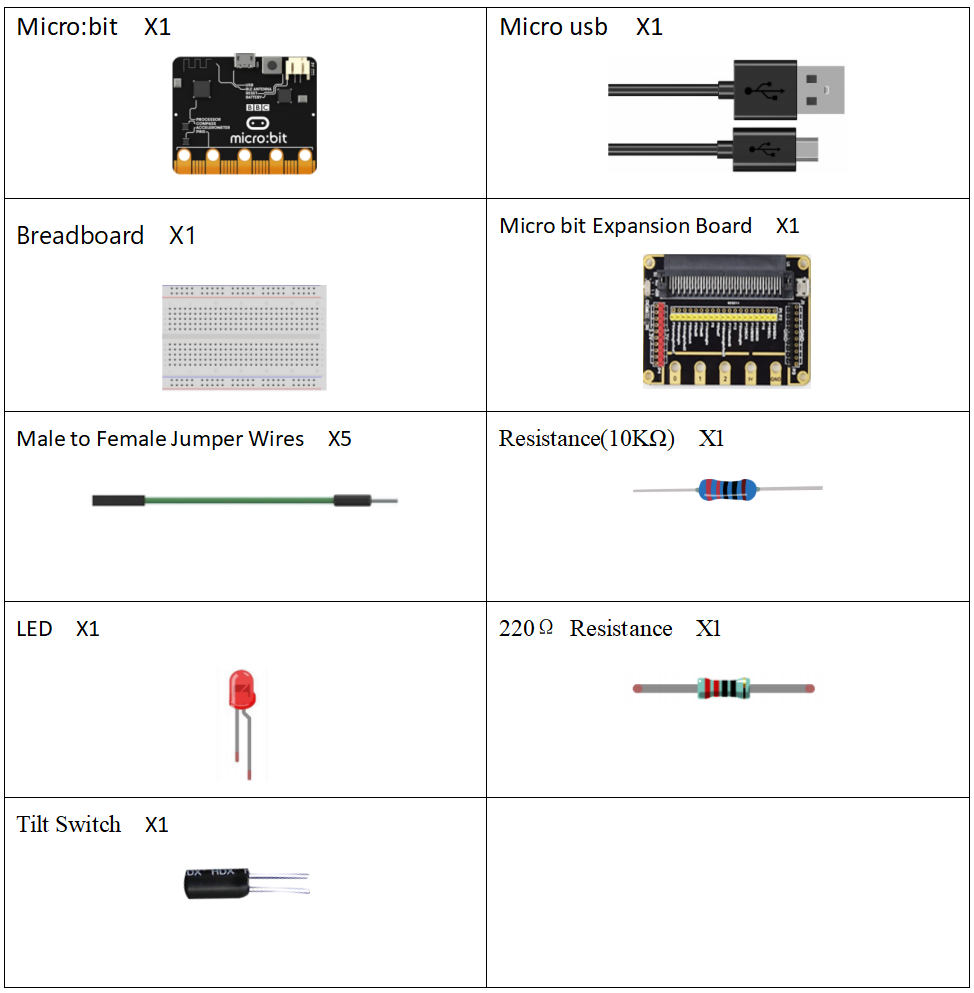
34.1 Components to be prepared
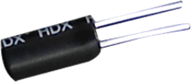
34.2 Tilt Switch
34.2.1 Tilt Switch
The tilt switch is also called a ball switch,which controls the connection or connection of the circuit with the principle of the ball rolling contact with the guide pin.The tilt switch is also called the ball switch.When the switch is tilted in the appropriate direction, the contacts will be connected, tilting the switch the opposite direction causes the metallic ball to move away from that set of contacts,thus breaking that circuit.
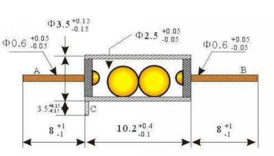
34.2.2 Working principle of tilt switch
The tilt switch is also called a ball switch, which controls the connection or disconnection of the circuit by the principle that the ball rolls on the guide pin.The tilt switch is also called the ball switch. When the switch is tilted in the appropriate direction, the contacts will be connected, tilting the switch the opposite direction causes the metallic ball to move away from that set of contacts, thus breaking that circuit.
34.3 Low level and high level
In circuit, the form of binary (0 and 1) is presented as low level and high level.
Low level is generally equal to ground voltage (0V). High level is generally equal to the operating voltage of components.
The low level of Micro:bit is 0V and high level is 3.3V, as shown below. When IO port on Micro:bit outputs high level, low-power components can be directly driven,like LED.

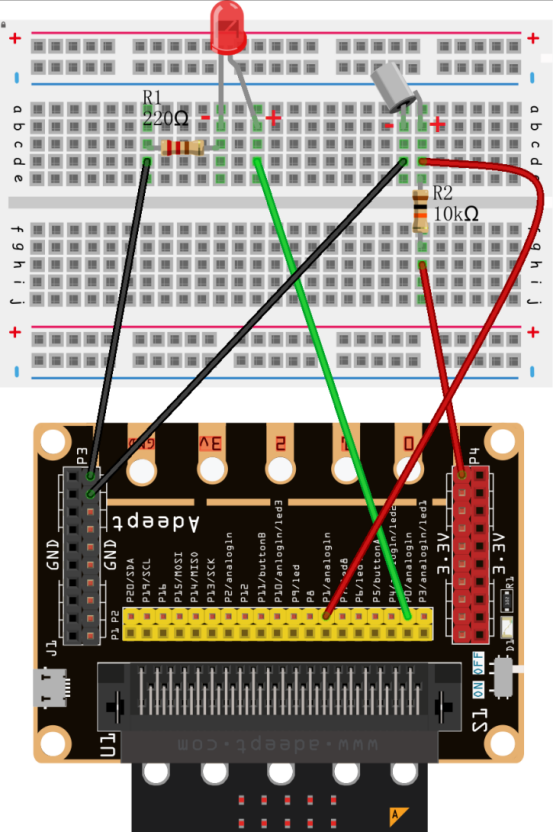
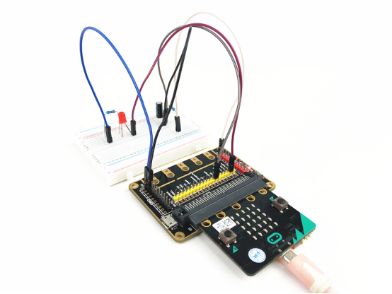
34.4 Circuit
You need to connect the components according to the following circuit diagram. You can use the “enlarge” function to view the picture.
34.5 MakeCode programming
Next, we will use the online MakeCode Editor to complete the experiment in this lesson.
34.5.1 Start programming
(1) Log in to the website
1. You need to enter the URL in the address bar of Google Browser:
https://makecode.microbit.org/
2. After the website is successfully opened, the interface as shown below will appear:

(2) Import a project
1. In the HOME interface, click the "Import" button to import the external ".hex" file:

In the pop-up dialog box, select the "Import File", as shown in the following figure:

Click the "Choose File"

Find the code file for this lesson:
BBC_Microbit_kit\Code\Lesson_34\BlockCode
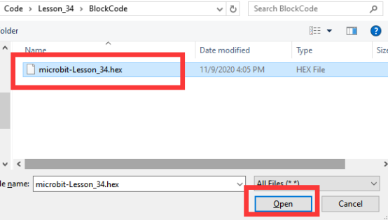
Select the file in ".hex" format and click the Open:
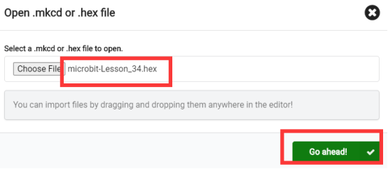
2. Notice whether the file has been loaded into the following window, and then click the "Go ahead!" button, as shown in the following figure:
3.You can see the following interface when successfully opening the file:
34.5.2 Run the program
1. After the program is written, connect micro:bit and PC with a Micro USB cable.
2. After micro:bit is connected to the computer, you need to first "Pair device". Click the  button on the right of
  in the lower left corner, and then click the
  option, as shown in the following figure:

Then click  in the lower right corner

Then the following dialog box will pop up, select  , and then click

After the device is successfully paired, the  button changes to

3. Start to download the program to Micro:bit, and click the  button. Generally, the program will be downloaded directly to the Micro:bit. After the download is completed, your Micro:bit will restart and run the program just downloaded. You need to tilt the tilt switch before you see the LED light up, as shown in the following figure:

[Note]:
1.If no experimental phenomenon has been detected after clicking the button  , you need to click the
  button on the right of the
  , and then click the
  , and observe the LED again, as shown in the following figure:

2.If there is still no experimental phenomenon, you need to unplug and then plug in the USB cable connected to the Micro:bit, and then download the program again.
3. If the LED does not change when you tilt the tilt switch, please check whether the wiring of the tilt switch and LED is wrong or loose.
If you have problems, please send us an email: support@adeept.com
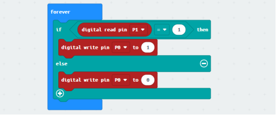
34.5.3 Learn the code program
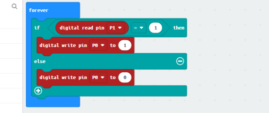
The tilt switch is connected to the P1 pin (represented by pin1), and the pin1.read_digital() is used to obtain the state of the pin1 (return values are 0 and 1: 0 indicates that the circuit is disconnected, and 1 indicates that the circuit is connected). If the circuit is connected due to the tilt or vibration of the tilt switch, there will be current passing through the pin1. The pin1 will generate a high level signal (high level is indicated by 1), and then you can light up the LED by setting the pin0 of the LED as high level (indicated by 1). Otherwise, the LED will be turned off.
34.6 Python programming
34.6.1 Run the program
1.Connect micro:bit and PC with a Micro USB cable.
2. Open the Mu Editor installed on the computer, and click the button [Load] in the upper left corner to open the source code program of this lesson:

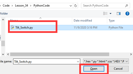
Find the code file for this lesson:
BBC_Microbit_Kit\Code\Lesson_34\PythonCode
Select the file in ".py" format and click the Open:
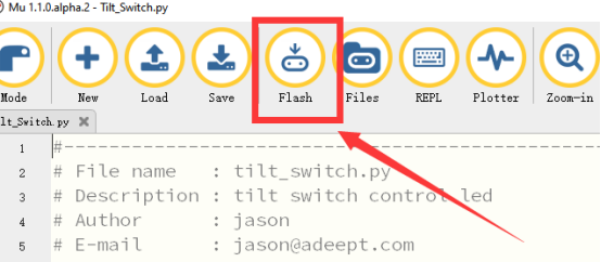
3. Click the [Flash] button to download the program to Micro:bit, as shown in the following figure:
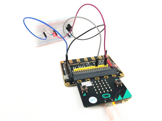
4.After downloading the program, you need to tilt the tilt switch before the LED lights up, as shown in the following figure:

【Note】:
If the LED does not change when you tilt the tilt switch, please check whether the wiring of the tilt switch and LED is wrong or loose.
If you have problems, please send us an email: support@adeept.com
34.5.2 Learn the code program
The codes for this lesson are explained as follows.
The tilt switch is connected to the P1 pin (represented by pin1), and the pin1.read_digital() is used to obtain the state of the pin1 (return values are 0 and 1: 0 indicates that the circuit is disconnected, and 1 indicates that the circuit is connected). If the circuit is connected due to the tilt or vibration of the tilt switch, there will be current passing through the pin1. The pin1 will generate a high level signal (high level is indicated by 1), and then you can light up the LED by setting the pin0 of the LED as high level (indicated by 1). Otherwise, the LED will be turned off.
1 2 3 | while True: #if pin1.read_digital() == 1 if pin1.read_digital(): pin0.write_digital(1) else: pin0.write_digital(0) sleep(10) |