In this lesson, we will carry out an interesting experiment to read the data on a 4x4 Matrix Keypad with a Micro:bit.
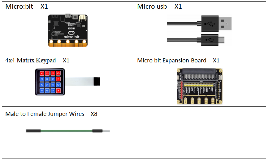
30.1 Components to be prepared
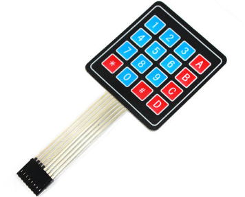
30.2 4x4 Matrix Keypad
30.2.1 4x4 Matrix Keypad
The 4x4 matrix keyboard is a keyboard set arranged in a matrix used in Micro:bit external devices. In a 4*4 matrix keyboard, each horizontal and vertical line is not connected directly at the intersection, but is connected by a single key. In this way, a port (such as port P1) can form 4*4=16 keys, which is twice as much as using port line for keyboard directly. Moreover, the more lines, the more obvious the difference is. For example, one more line can form a 20-key keyboard, while using port line can only create one more key (9 keys). Thus it can be seen that it is reasonable to use the matrix method to make the keyboard when the number of keys needed is large.
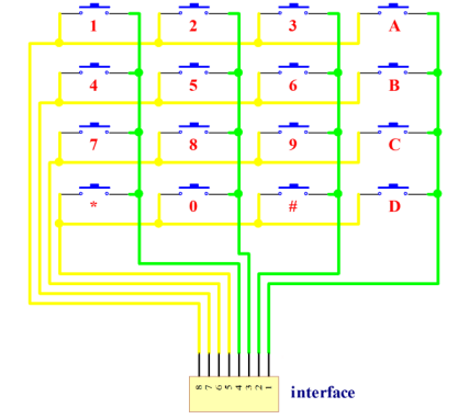
30.2.2 The working principle of the 4*4 Matrix Keyboard
The keys are arranged at the intersection of the row and column lines, and the row and column lines are connected to both ends of the key switch respectively. When the key is not pressed, all input terminals are high level, which means no key is pressed. The line output is low level. Once a key is pressed, the input line will be pulled down. In this way, you can know whether a key is pressed by reading the state of the input line. The line is connected to the +5V power supply through a pull-up resistor.
A "line scan method" is used to determine which key on the matrix keyboard is pressed
Step 1: make the line the input line of programming and the column line the output line, pull down all the column lines, and judge the change of the line. If there is a key pressed, the corresponding line pressed will be pulled down, otherwise all the line lines will be at high level.
Step 2:after the first step is judged to have a key pressed, the mechanical jitter will be eliminated after a delay of 10ms, and the row value will be read again. If the line is still at a low level, the next step will be entered; otherwise, the first step will be returned to re-judge.
Step 3: start scanning the position of the key, and use line by line scanning. Every 1ms interval, pull down the first column, the second column, the third column and the fourth column respectively. No matter which column you lower, the other three columns are at high level. Read the row value to find the location of the key and store the row and column values in it.
Step 4:find the row value and the column value from the register and combine them to get the key value, which is coded from the first row to the fourth row from the first row to the fourth row, from "0000" to "1111", and then display Decode. Finally, the key number is displayed. Principle of dynamic scanning of digital tube: the 7 segments and the decimal point of the digital tube are all composed of LED blocks, and the display mode is divided into static display and dynamic display. When the digital tube is displayed in static mode, the bit selection signals of its total positive tube are all low level, and the common segment selection lines of the four digital tubes a, b, c, d, e, f, g and dp are respectively connected with the 8 I/O port lines of CPLD. When the digital tube is displayed, only the low level should be sent to the corresponding segment selection line. Dynamic display of digital tube in the way, there can be only one at a time to light the digital tube display digital, the rest is in a state of the gate, a selected code port signal changes, port signal segment code also should make corresponding change. The stay time of each Character is usually 1-5 ms, using visual inertia, one eye can see fairly stable on the digital tube digital display.
30.3 Low level and high level
In circuit, the form of binary (0 and 1) is presented as low level and high level.
Low level is generally equal to ground voltage (0V). High level is generally equal to the operating voltage of components.
The low level of Micro:bit is 0V and high level is 3.3V, as shown below. When IO port on Micro:bit outputs high level, low-power components can be directly driven,like LED.

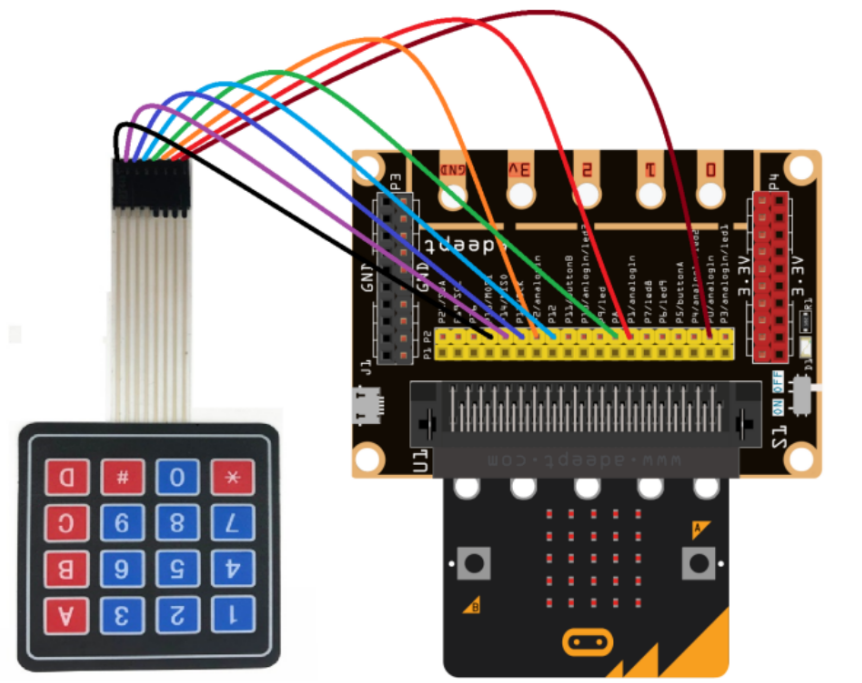
30.4 Circuit
You need to connect the components according to the following circuit diagram. You can use the “enlarge” function to view the picture.
30.5 MakeCode programming
Next, we will use the online MakeCode Editor to complete the experiment in this lesson.
30.5.1 Start programming
(1) Log in to the website
1. You need to enter the URL in the address bar of Google Browser:
https://makecode.microbit.org/
2. After the website is successfully opened, the interface as shown below will appear:

(2) Import a project
1. In the HOME interface, click the "Import" button to import the external ".hex" file:

In the pop-up dialog box, select the "Import File", as shown in the following figure:

Click the "Choose File"

Find the code file for this lesson:
BBC _Microbit_Kit\Code\Lesson_30\BlockCode
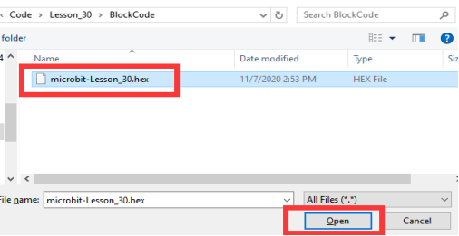
Select the file in ".hex" format and click the Open:
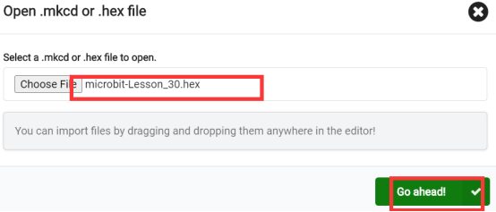
2. Notice whether the file has been loaded into the following window, and then click the "Go ahead!" button, as shown in the following figure:
3.You can see the following interface when successfully opening the file:
30.5.2 Run the program
1. After the program is written, connect micro:bit and PC with a Micro USB cable.
2. After micro:bit is connected to the computer, you need to first "Pair device". Click the  button on the right of
  in the lower left corner, and then click the
  option, as shown in the following figure:

Then click  in the lower right corner

Then the following dialog box will pop up, select  , and then click

After the device is successfully paired, the  button changes to

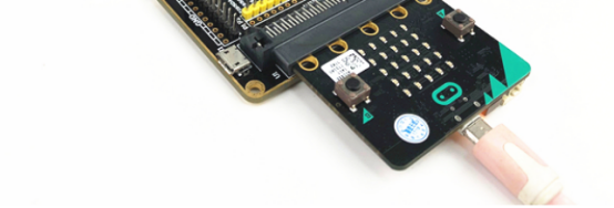
3.Then click the  button to directly download the program into the Micro:bit. After the download is finished, your Micro:bit will restart and run the program you just downloaded. You need to press and hold the key on the 4x4 matrix keyboard (due to the delay in the MakeCode, you need to press and hold the key until the corresponding key value is displayed on the Micro:bit), as shown in the following figure:

[Note]
1.If no experimental phenomenon is observed after the  is clicked, you need to click the
  button on the right of the
  , then click the
  and observe the Micro:bit again, as shown in the following figure:

2.If there is still no experimental phenomenon, you need to unplug and then plug in the USB cable connected to the Micro:bit, and then download the program again.
If you have problems, please send us an email: support@adeept.com
30.5.3 Learn the code program
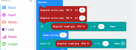
Pins P0, P1, P2 and P8 represent rows, and pins P12, P13, P14 and P15 represent columns. The method to read the key value of the 4*4 matrix keyboard is as follows: write a signal on each row in turn. If a signal is input in any column, the corresponding key value will be displayed on the LED screen.
First send a signal 1 to the row connected on the P8 pin, and judge which key is pressed through an if statement. Then output the corresponding key value on the LED screen of the Micro:bit.

30.6 Python programming
30.6.1 Run the program
1.Connect micro:bit and PC with a Micro USB cable.
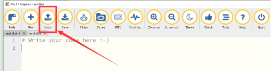
2. Open the Mu Editor installed on the computer, and click the button [Load] in the upper left corner to open the source code program of this lesson:
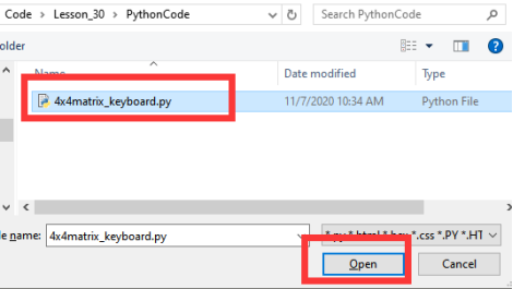
Find the code file for this lesson:
BBC _Microbit_Kit\Code\Lesson_30\PythonCode
Select the file in ".py" format and click the Open:
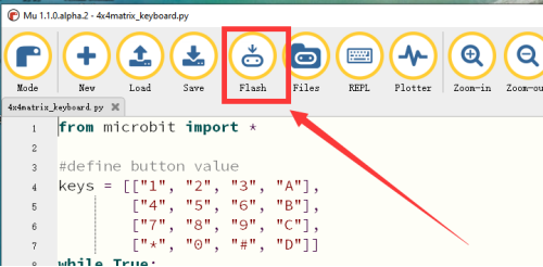
3. Click the [Flash] button to download the program to Micro:bit, as shown in the following figure:
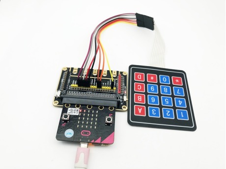
4.After downloading the program, you need to press the key on the 4x4 matrix keyboard. The LED screen of the Micro:bit will display the corresponding key value, as shown in the following figure.
【Note】:
If the corresponding key value is not displayed or the wrong key value is displayed on the screen of the Micro:bit, please check whether the wiring is wrong or loose.
If you have problems, please send us an email: support@adeept.com
30.6.2 Learn the code program
(1)define button value.
4 5 6 7 | keys = [["1", "2", "3", "A"], ["4", "5", "6", "B"], ["7", "8", "9", "C"], ["*", "0", "#", "D"]] |
(2) Input a signal in each row and column separately.
11 12 13 14 15 16 17 18 | pin12.read_digital() pin13.read_digital() pin14.read_digital() pin15.read_digital() pin0.write_digital(1) pin1.write_digital(1) pin2.write_digital(1) pin8.write_digital(1) |
(3)Check row button.
20 21 22 23 24 25 26 27 28 29 | row = pin12.read_digital() + pin13.read_digital()*2 + \ pin14.read_digital()*3 + pin15.read_digital()*4 pin0.read_digital() pin1.read_digital() pin2.read_digital() pin8.read_digital() pin12.write_digital(1) pin13.write_digital(1) pin14.write_digital(1) pin15.write_digital(1) |
(4)Check column button.
31 32 33 34 35 | column = pin0.read_digital() + pin1.read_digital()*2 + \ pin2.read_digital()*3 + pin8.read_digital()*4 if(column+row != 0): display.scroll(str(keys[colume-1][row-1])) sleep(100) |