In this lesson, we will carry out an interesting experiment to display information on an LCD1602 with a Micro:bit.
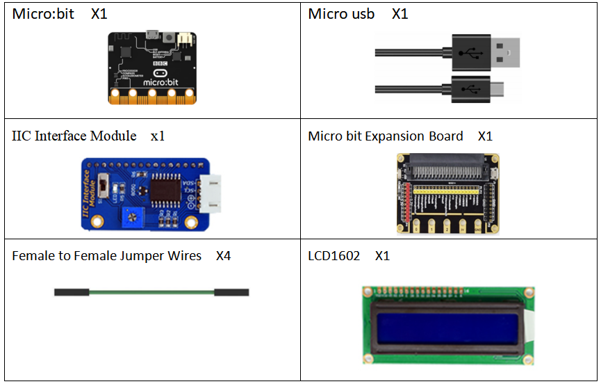
25.1 Components to be prepared
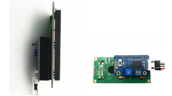
25.2 LCD1602 and IIC Interface Module
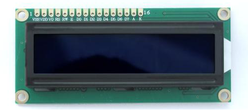
25.2.1 LCD1602
LCD1602 liquid crystal display is a character liquid crystal display module widely used.It is composed of a character liquid crystal display (LCD),a main control circuit HD44780 and its extended drive circuit HD44100,and a small number of resistors, capacitors, and structural parts, etc., which are assembled on a PCB.
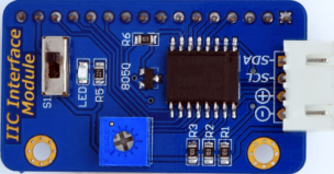
25.2.2 IIC Interface Module
IIC "Inter-Integrated Circuit" is a serial communication bus used for communication between low-speed devices on board. The purpose of this communication protocol developed by Philips is to simplify the system hardware design and reduce the connections between devices. IIC can reduce the number of pins occupied by LCD1602, and reduce the number of pins to two.
25.2.3 Working principle of the LCD1602
The LCD1602 character liquid crystal display module is a dot-matrix LCD specifically for displaying letters, numbers, and symbols. Commonly used modules are 16×1, 16×2, 20×2, and 40×2. The internal controller of the general LCD1602 character liquid crystal display is mostly HD44780, which can display English letters, Arabic numerals, Japanese Katakana and general symbols.
LCD1602 is a kind of character LCD display. The LCD has a parallel interface, meaning that the microcontroller has to manipulate several interface pins at once to control the display. The interface consists of the following pins:
● A register select (RS) pin that controls where in the LCD's memory you're writing data to. You can select either the data register, which holds what goes on the screen, or an instruction register, which is where the LCD's controller looks for instructions on what to do next.
● A Read/Write (R/W) pin that selects reading mode or writing mode
● An Enable pin that enables writing to the registers
● 8 data pins (D0-D7). The state of these pins (high or low) is the bits that you're writing to a register when you write, or the values when you read.
● There are also a display contrast pin (Vo), power supply pins (+5V and Gnd) and LED Backlight (Bklt+ and BKlt-) pins that you can use to power the LCD, control the display contrast, and turn on or off the LED backlight respectively.
The process of controlling the display involves putting the data that form the image of what you want to display into the data registers, then putting instructions in the instruction register. The LiquidCrystal Library simplifies this for you so you don't need to know the low-level instructions.
The Hitachi-compatible LED can be controlled in two modes: 4-bit or 8-bit. The 4-bit mode requires seven I/O pins from the Arduino, while the 8-bit mode requires 11 pins. For displaying text on the screen, you can do most everything in 4-bit mode, so example shows how to control a 2x16 LCD in 4-bit mode.
25.3 Low level and high level
In circuit, the form of binary (0 and 1) is presented as low level and high level.
Low level is generally equal to ground voltage (0V). High level is generally equal to the operating voltage of components.
The low level of Micro:bit is 0V and high level is 3.3V, as shown below. When IO port on Micro:bit outputs high level, low-power components can be directly driven,like LED.

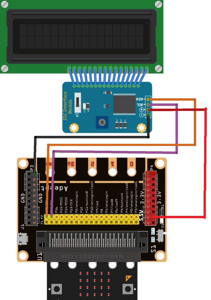
25.4 Circuit
You need to connect the components according to the circuit diagram below. You can use the “enlarge” function to view the picture: the “+” of the IIC interface module must be connected to the “5.5V” pin on the Micro bit Expansion Board, and an external power supply is required.
25.5 MakeCode programming
Next, we will use the online MakeCode Editor to complete the experiment in this lesson.
25.5.1 Start programming
(1) Log in to the website
1. You need to enter the URL in the address bar of Google Browser:
https://makecode.microbit.org/
2. After the website is successfully opened, the interface as shown below will appear:

(2) Import a project
1. In the HOME interface, click the "Import" button to import the external ".hex" file:

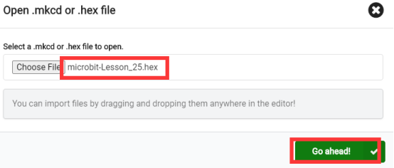
In the pop-up dialog box, select the "Import File", as shown in the following figure:

Click the "Choose File"

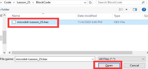
Find the code file for this lesson:
BBC _Microbit_Kit\Code\Lesson_25\BlockCode
Select the file in ".hex" format and click the Open:
2. Notice whether the file has been loaded into the following window, and then click the "Go ahead!" button, as shown in the following figure:
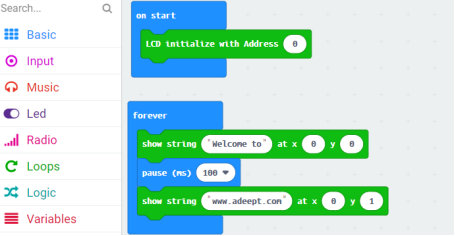
3.You can see the following interface when successfully opening the file:
25.5.2 Run the program
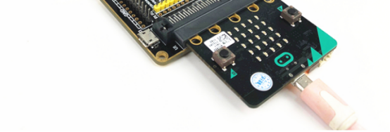
1. After the program is written, connect micro:bit and PC with a Micro USB cable.
2. After micro:bit is connected to the computer, you need to first "Pair device". Click the  button on the right of
  in the lower left corner, and then click the
  option, as shown in the following figure:

Then click  in the lower right corner

Then the following dialog box will pop up, select  , and then click

After the device is successfully paired, the  button changes to

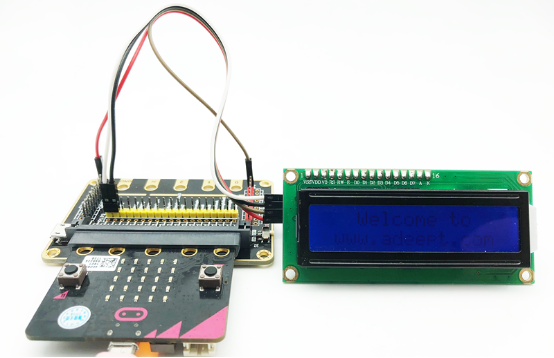
3. Start to download the program to Micro:bit, and click the  button. Generally, the program will be downloaded directly to the Micro:bit. After the download is completed, your Micro:bit will restart and run the program just downloaded.Observe whether the LCD1602 screen displays text information, as shown in the following figure:
[Note]
1.If the LCD1602 screen doesn’t display text information after the  is clicked, you need to click the
  button on the right of the
  , then click the
  and observe the Micro:bit again, as shown in the following figure:

2.If the LCD1602 screen still doesn’t display text information, you need to unplug and then plug in the USB cable connected to the Micro:bit, and then download the program again.
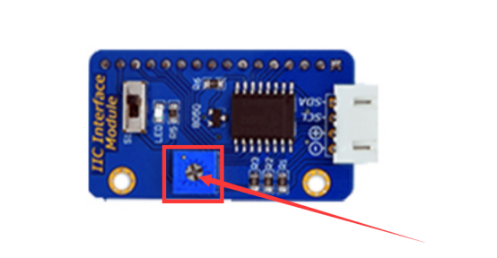
3.After the program is executed, if you cannot see anything on the display or the display is not clear,try rotating the white knob on back of IIC Interface Module slowly, which adjusts the contrast, until the screen can display the Temperature clearly.

If you have problems, please send us an email: support@adeept.com
25.5.3 Learn the code program
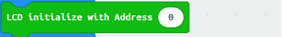
(1)LCD initialization,If you enter 0, it will automatically search for the correct I2C address and connect.
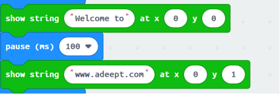
(2)The string is displayed on the LCD1602 screen:
[Note]
If you want to import the LCD1602 expansion block in a new project, follow the steps below to add it.
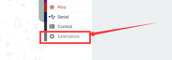
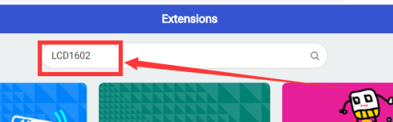
(1)Click the [extensions] button:
(2)Input “LCD1602”, and then click the search.
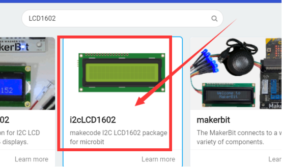
(3)Select the “i2cLCD1602”.
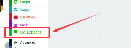
(4)the LCD1602 expansion block is added successfully:
25.6 Python programming
25.6.1 Run the program
1.Connect micro:bit and PC with a Micro USB cable.
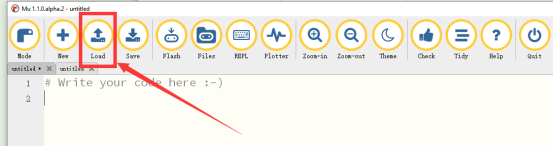
2. Open the Mu Editor installed on the computer, and click the button [Load] in the upper left corner to open the source code program of this lesson:
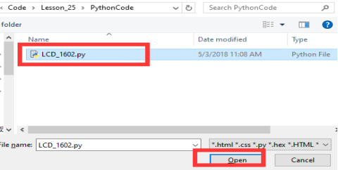
Find the code file for this lesson:
BBC _Microbit_Kit\Code\Lesson_25\PythonCode
Select the file in ".py" format and click the Open:
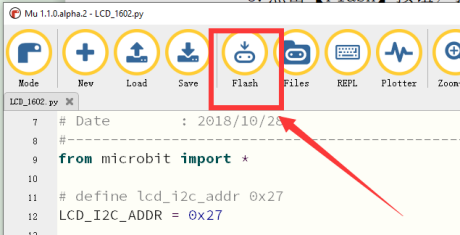
3. Click the [Flash] button to download the program to Micro:bit, as shown in the following figure:
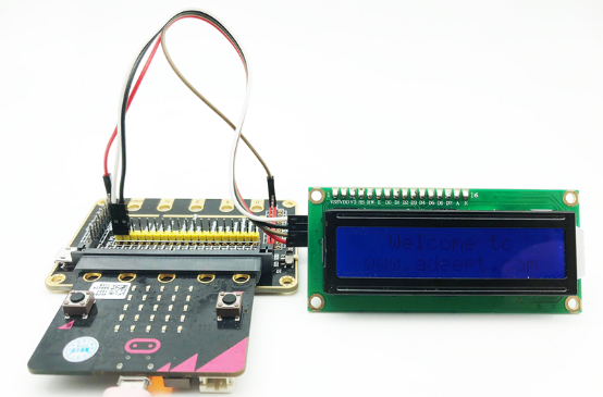
4.After the program is downloaded, observe whether the LCD1602 screen shows text, as shown in the following figure.
【Note】:
(1)If your LCD1602 screen does not display clear text information, you need to use Micro USB cable to power the external power supply of the Micro bit Expansion Board.
(2)After the program is executed, if you cannot see anything on the display or the display is not clear,try rotating the white knob on back of IIC Interface Module slowly, which adjusts the contrast, until the screen can display the Temperature clearly.
If you have problems, please send us an email: support@adeept.com
25.6.2 Learn the code program
The codes for this lesson are explained as follows.
(1)Since the I2C addresses of LCD1602 of various manufacturers are different (usually one of these two addresses: 0x27 and 0x3F), all equipment addresses are found through scan command, and then the I2C addresses of acceleration sensor and magnetic sensor (29 and 14) are excluded. Finally, the address of newly added I2C equipment is obtained.
3 11 12 13 | LCD_I2C_ADDR = 0x0 for i in i2c.scan(): if i not in [14, 29]: LCD_I2C_ADDR = i |
(2)The method of LCD1602() can be used to show information on the LCD1602.
87 88 89 | sh = LCD1602() sh.puts(" Welcome to") sh.puts(" www.adeept.com", 0, 1) |
【API】
(1)puts(s, x, y)
show a string in given position.
x: 0-15
y: 0-1
(2)char(ch, x, y)
show a character in given position.
x: 0-15
y: 0-1
(3)backlight(on)
on=0: turn of backlight
on=1: turn on backlight
(4)clear()
clear display.
(5)off()
turn off LCD.
(6)on()
turn on LCD.