In this lesson, we will carry out an interesting experiment to control a passive buzzer to play a custom music with a Micro:bit.
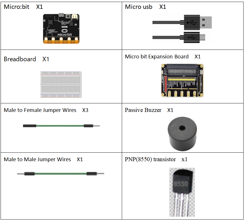
24.1 Components to be prepared
24.2 The introduction of the Buzzer
24.2.1 The Buzzer
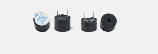
The Buzzer is an electronic sounder with an integrated structure. It is powered by DC voltage and is widely used as a sounding device in electronic products such as computers, printers, copiers, alarms, electronic toys, automotive electronic equipment, telephones, timers, and other electronic products. . There are two types of buzzer: active buzzer and passive buzzer. As shown in the figure below, the left is the active buzzer (the two pins have different lengths), and the right is the passive buzzer (the two pins have the same length).
24.2.2 Working principle of the Buzzer
The sounding principle of buzzer is composed of vibration device and resonance device, and buzzer is divided into passive buzzer and active buzzer. The working sounding principle of passive buzzer is: square wave signal input resonant device is converted into sound signal output; the working sounding principle of active buzzer is: DC power input is generated by the amplification sampling circuit of the oscillation system under the action of the resonance device Sound signal. Our course in this section uses an active buzzer. As long as the power is on, the active buzzer will sound. We can program the Micro:bit output high and low alternately, so that the active buzzer will sound.
24.2.3 Two kinds of Transistors (S8050 and S8550)
To make the active buzzer sound, a large current is required. However, the output current of Micro:bit development board is very weak, so we need a transistor S8050 or S8550 to drive the active buzzer. The main function of the transistor S8050 (S8550) is to amplify the voltage or current, and it can also be used to control the conduction or cut-off time of the circuit.
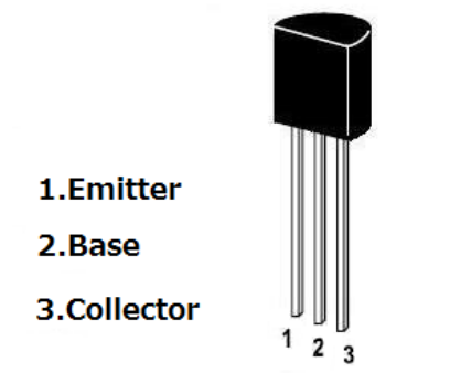
There are two kinds of transistors, one is NPN, such as the transistor S8050 used in our course; the other is a PNP transistor, such as the other S8550 we provide. The pin structure of the two transistors we use is the same. Their pin structure is as shown in the figure below. In the circuit, Emitter is abbreviated as e, Base is abbreviated as b, and Collector is abbreviated as c.
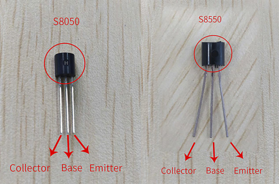
The S8050 and S8550 transistors provided by our course are as shown below. The letter H is S8050, and the letter H is S8550.
The transistors S8050 and S8550 and the buzzer are connected in the circuit as shown below:
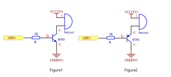
Figure1:
Set the Micro:bit as a high level, the transistor S8050 will conduct, and then the buzzer will sound; set the Micro:bit as low level, the transistor S8050 will cut off, then the buzzer will stop.
Figure2:
Set the Micro:bit as low level, the transistor S8550 will conduct, and the buzzer will sound; set the Micro:bit as a high level, the transistor S8550 will cut off, then the buzzer will stop.
24.3 Low level and high level
In circuit, the form of binary (0 and 1) is presented as low level and high level.
Low level is generally equal to ground voltage (0V). High level is generally equal to the operating voltage of components.
The low level of Micro:bit is 0V and high level is 3.3V, as shown below. When IO port on Micro:bit outputs high level, low-power components can be directly driven,like LED.

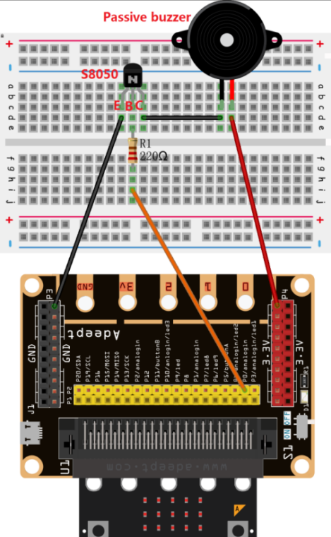
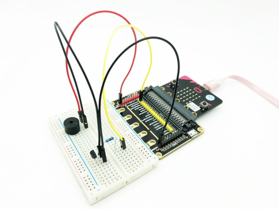
24.4 Circuit
You need to connect the components according to the following circuit diagram. You can use the “enlarge” function to view the picture.
24.5 MakeCode programming
Next, we will use the online MakeCode Editor to complete the experiment in this lesson.
24.5.1 Start programming
(1) Log in to the website
1. You need to enter the URL in the address bar of Google Browser:
https://makecode.microbit.org/
2. After the website is successfully opened, the interface as shown below will appear:

(2) Import a project
1. In the HOME interface, click the "Import" button to import the external ".hex" file:

In the pop-up dialog box, select the "Import File", as shown in the following figure:

Click the "Choose File"

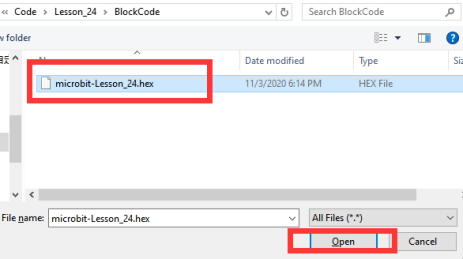
Find the code file for this lesson:
BBC _Microbit_Kit\Code\Lesson_24\BlockCode
Select the file in ".hex" format and click the Open:
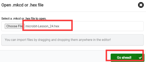
2. Notice whether the file has been loaded into the following window, and then click the "Go ahead!" button, as shown in the following figure:
3.You can see the following interface when successfully opening the file:
24.5.2 Run the program
1. After the program is written, connect micro:bit and PC with a Micro USB cable.
2. After micro:bit is connected to the computer, you need to first "Pair device". Click the  button on the right of
  in the lower left corner, and then click the
  option, as shown in the following figure:

Then click  in the lower right corner

Then the following dialog box will pop up, select  , and then click

After the device is successfully paired, the  button changes to

3. Start to download the program to Micro:bit, and click the  button. Generally, the program will be downloaded directly to the Micro:bit. After the download is completed, your Micro:bit will restart and run the program just downloaded.Listen to whether the passive buzzer plays music, as shown in the following figure:
[Note]
1.If the passive buzzer doesn’t play music after the  is clicked, you need to click the
  button on the right of the
  , then click the
  and observe the Micro:bit again, as shown in the following figure:

2.If the passive buzzer still doesn’t play music, you need to unplug and then plug in the USB cable connected to the Micro:bit, and then download the program again.
If you have problems, please send us an email: support@adeept.com
24.5.3 Learn the code program
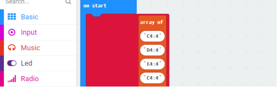
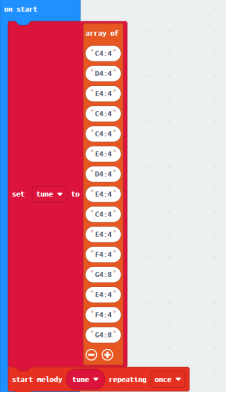
The tune array holds a custom melody, and each element in the array contains notes and beats. For example,"A1:4" refers to the note named A in octave number 1 to be played for a duration of 4.
More information about the Musical Notation is available in the following link:
https://microbit-micropython.readthedocs.io/en/v1.0.1/music.html
24.6 Python programming
24.6.1 Run the program
1.Connect micro:bit and PC with a Micro USB cable.
2. Open the Mu Editor installed on the computer, and click the button [Load] in the upper left corner to open the source code program of this lesson:
![]()
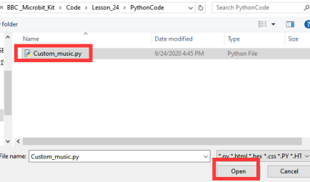
Find the code file for this lesson:
BBC _Microbit_Kit\Code\Lesson_24\PythonCode
Select the file in ".py" format and click the Open:
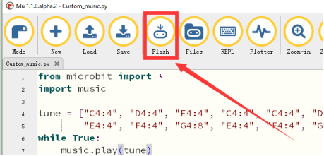
3. Click the [Flash] button to download the program to Micro:bit, as shown in the following figure:
4.After the program is downloaded, listen to whether the passive buzzer plays music, as shown in the following figure.

If you have problems, please send us an email: support@adeept.com
24.6.2 Learn the code program
(1)The tune array holds a custom melody, and each element in the array contains notes and beats. For example,"A1:4" refers to the note named A in octave number 1 to be played for a duration of 4..
4 5 6 7 | tune = ["C4:4", "D4:4", "E4:4", "C4:4", "C4:4", "D4:4", "E4:4", "C4:4", "E4:4", "F4:4", "G4:8", "E4:4", "F4:4", "G4:8"] while True: music.play(tune) |
More information about the Musical Notation is available in the following link:
https://microbit-micropython.readthedocs.io/en/v1.0.1/music.html