In this lesson, we will carry out an interesting experiment to change the color of a RGB LED with a Micro:bit.
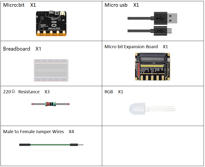
19.1 Components to be prepared
19.2 RGB LED
19.2.1 RGB
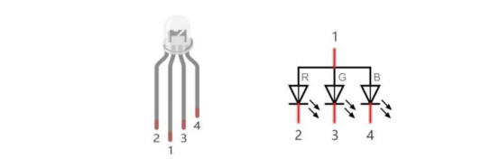
A RGB LED has 3 LEDs integrated into one LED component. It can respectively emit Red, Green and Blue light.
In order to do this, it requires 4 pins (this is also how you identify it). The long pin (1) is the common which is the Anode (+) or positive lead, the other 3 are the Cathodes (-) or negative leads. A rendering of a RGB LED and its electronic symbol are shown below. We can make RGB LED emit various colors of light and brightness by controlling the 3 Anodes (2, 3 & 4) of the RGB LED .
Red, Green, and Blue light are called 3 Primary Colors when discussing light (Note: for pigments such as paints, the 3 Primary Colors are Red, Blue and Yellow). When you combine these three Primary Colors of light with varied brightness, they can produce almost any color of visible light. Computer screens, single pixels of cell phone screens, neon lamps, etc. can all produce millions of colors due to phenomenon.
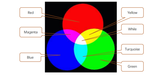
If we use a three 8 bit PWM to control the RGB LED, in theory, we can create 28*28*28=16777216 (16 million) colors through different combinations of RGB light brightness.
19.2.2 HSL color
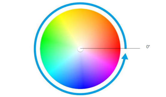
The HSL color mode is another color standard in the industry. It obtains a variety of colors by changing the three color channels of hue (H), saturation (S), and lightness (L) and superimposing them with each other. This color mode covers almost all colors that human vision can perceive. It is one of the most widely used color systems to date.
As shown in the hue circle below, the 0 degree of the hue is R (red) color, 120 degrees is G (green) color, and 240 degrees is B (blue) color. Each angle represents a color. The default saturation (S) takes the maximum value 100, the brightness (L) takes 50. If the hue angle is changed, the color will be changed. And the HSL color system can be converted to the RGB color system, to change the color of the LED.
19.3 Low level and high level
In circuit, the form of binary (0 and 1) is presented as low level and high level.
Low level is generally equal to ground voltage (0V). High level is generally equal to the operating voltage of components.
The low level of Micro:bit is 0V and high level is 3.3V, as shown below. When IO port on Micro:bit outputs high level, low-power components can be directly driven,like LED.

19.4 Circuit
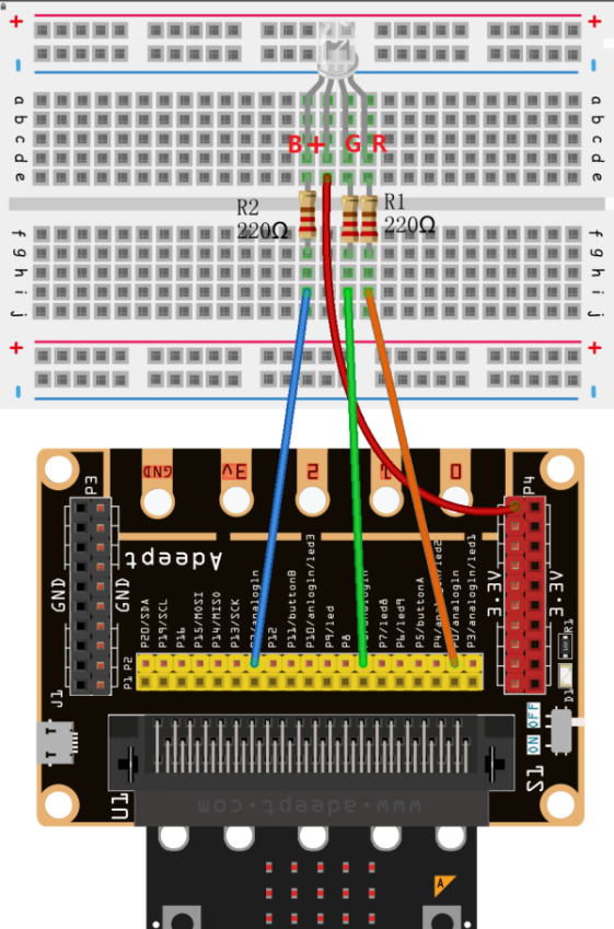
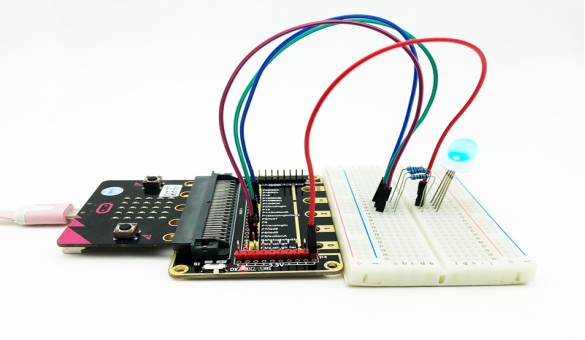
You need to connect the components according to the circuit diagram below. The resistance used is 220Ω. Connect the positive and negative poles of the LED with the breadboard correctly.
19.5 MakeCode programming
Next, we will use the online MakeCode Editor to complete the experiment in this lesson.
19.5.1 Start programming
(1) Log in to the website
1. You need to enter the URL in the address bar of Google Browser:
https://makecode.microbit.org/
2. After the website is successfully opened, the interface as shown below will appear:

(2) Import a project
1. In the HOME interface, click the "Import" button to import the external ".hex" file:

In the pop-up dialog box, select the "Import File", as shown in the following figure:

Click the "Choose File"

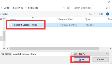
Find the code file for this lesson:
BBC _Microbit_Kit\Code\Lesson_19\BlockCode
Select the file in ".hex" format and click the Open:
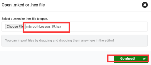
2. Notice whether the file has been loaded into the following window, and then click the "Go ahead!" button, as shown in the following figure:
3.You can see the following interface when successfully opening the file:
19.5.2 Run the program
1. After the program is written, connect micro:bit and PC with a Micro USB cable.
2. After micro:bit is connected to the computer, you need to first "Pair device". Click the  button on the right of
  in the lower left corner, and then click the
  option, as shown in the following figure:

Then click  in the lower right corner

Then the following dialog box will pop up, select  , and then click

After the device is successfully paired, the  button changes to

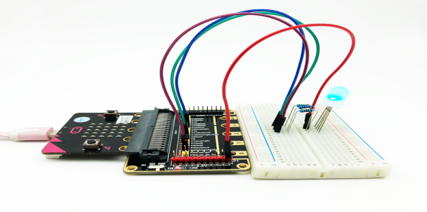
3. Start to download the program to Micro:bit, and click the  button. Generally, the program will be downloaded directly to the Micro:bit. After the download is completed, your Micro:bit will restart and run the program just downloaded.If the color of the RGB LED on the breadboard changes, it indicates the success of the experiment, as shown in the following figure:
[Note]
1.If the RGB LED on the breadboard has no change in color after the  is clicked, you need to click the
  button on the right of the
  , then click the
  and observe the Micro:bit again, as shown in the following figure:

2.If the RGB LED on the breadboard still has no change in color, you need to unplug and then plug in the USB cable connected to the Micro:bit, and then download the program again.
If you have problems, please send us an email: support@adeept.com
19.5.3 Learn the code program
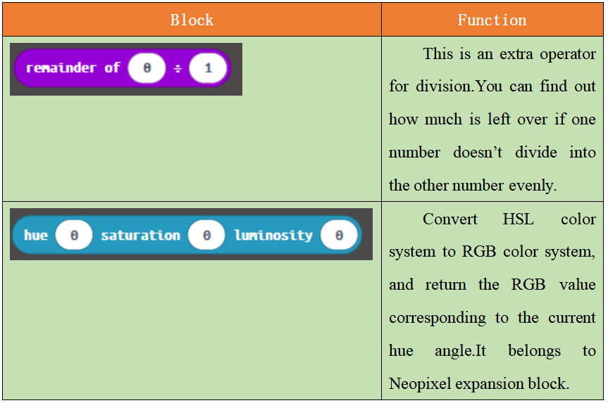
The following instruction blocks will be applied in the program. Please see the description of the function as follows:
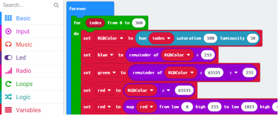
(1)From the knowledge of HSL color,we can know that different hue angles correspond different colors.The variable index represents hue angle,ranging from 0 to 360.

(2)This block is to convert the HSL color system to the RGB color system,return the RGB value corresponding to the current hue angle,and store the value in the variable RGB Color.For example:hexadecimal RGB value 0xFF0000 means red,FF is the value of the red channel in RGB,and 00 and 00 are the values of the green and blue channels, respectively.

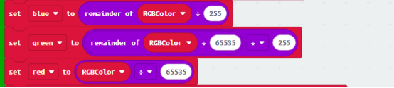
(3)Assign the value of the lower eight-bit to blue channel, the value of the middle eight-bit to green channel,and the value of the upper eight-bit to red channel.
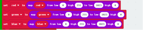
(4)In this kit, three LEDs of RGB LED share a common anode (+) and their negative pins need to be set to LOW level to have the RGB LED work. And the variables ‘red’, ‘green’, and ‘blue’ need to be converted from the value ranging from 0-255 to analog signal values ranging from1023-0.
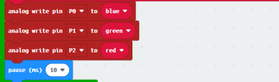
(5)Every 10ms, write the‘red’,‘green’,‘blue’to corresponding pins P2, P1,P0.
19.6 Python programming
19.6.1 Run the program
1.Connect micro:bit and PC with a Micro USB cable.
2. Open the Mu Editor installed on the computer, and click the button [Load] in the upper left corner to open the source code program of this lesson:

Find the code file for this lesson:
BBC _Microbit_Kit\Code\Lesson_19\PythonCode
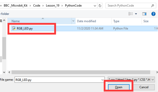
Select the file in ".py" format and click the Open:
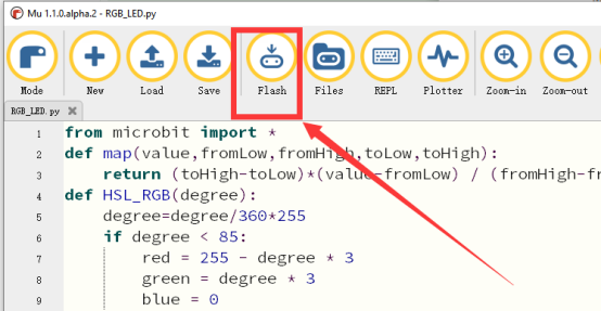
3. Click the [Flash] button to download the program to Micro:bit, as shown in the following figure:
4. After the program is downloaded, if the color of the RGB LED on the breadboard changes, it indicates the success of the experiment, as shown in the following figure.
If you have problems, please send us an email: support@adeept.com
19.6.2 Learn the code program
(1)The map() function is used to convert a value in one range to another range.
2 3 | def map(value,fromLow,fromHigh,toLow,toHigh): return (toHigh-toLow)*(value-fromLow) / (fromHigh-fromLow) + toLow |
(2)The HSL_RGB() function is used to convert the HSL color system to RGB color, and return the RGB value corresponding to the current hue angle.
4 5 6 7 8 9 10 11 12 13 14 15 16 17 18 19 20 | def HSL_RGB(degree): degree=degree/360*255 if degree < 85: red = 255 - degree * 3 green = degree * 3 blue = 0 elif degree < 170: degree = degree - 85 red = 0 green = 255 - degree * 3 blue = degree * 3 else: degree = degree - 170 red = degree * 3 green = 0 blue = 255 - degree * 3 return red,green,blue |
(3)Repeat 360 times, display the hue angle color corresponding to 0 to 360 degrees, and replace it every 10ms.
21 22 23 24 25 26 27 28 29 30 | while True: for i in range(360): red,green,blue=HSL_RGB(i) red=map(red,0,255,1023,0) green=map(green,0,255,1023,0) blue=map(blue,0,255,1023,0) pin2.write_analog(red) pin1.write_analog(green) pin0.write_analog(blue) sleep(10) |