In this lesson, we will carry out an interesting experiment to control a motor with a Micro:bit.
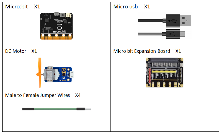
21.1 Components to be prepared
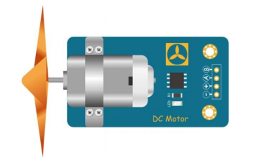
21.2 The introduction of the DC Motor
21.2.1 The DC Motor
A DC motor is a motor that converts DC electrical energy into mechanical energy. Because of its good speed regulation performance, it is widely used in electric towing. DC motors are divided into three categories: permanent magnet, other excitation, and self-excitation according to the excitation mode. Self-excitation is divided into three types: parallel excitation, series excitation, and compound excitation.
When DC power is supplied to the armature winding through the brush, the N-pole conductor on the surface of the armature can flow current in the same direction. According to the left-hand rule, the conductor will be subjected to counterclockwise torque; a part of the conductor under the S pole of the armature surface also flow current in the same direction, and the conductor will also be subjected to a counterclockwise moment according to the left-hand rule. In this way, the entire armature winding, that is, the rotor will rotate counterclockwise, and the input DC energy is converted into mechanical energy output on the rotor shaft. It is composed of stator and rotor, stator: base, main magnetic pole, commutation pole, and brush device, etc. rotor (armature): armature core, armature winding, commutator, rotating shaft and fan, etc.
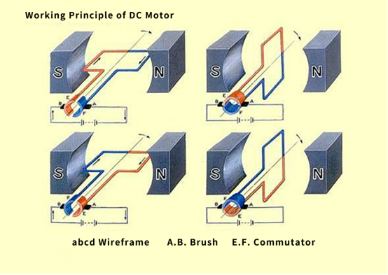
21.2.2 Working principle of the DC Motor
1.The DC power current flows along the positive pole of the power supply to the left brush. The brush and the commutator rub against each other. The current flows into the coil through the left commutator, flows out from the right side of the coil, and passes through the right commutator And the brush on the right flows back to the negative pole of the power supply, forming a closed loop.
2.Because the coil is in the magnetic field of the main magnetic pole, the coil will be subjected to the electromagnetic force. The two sides of the coil have different current directions (the current on the left flows inward and the right flows outward). Electromagnetic forces of the same magnitude and opposite directions, these two electromagnetic forces just form an electromagnetic torque. Under the pulling of the electromagnetic torque, the coil starts to rotate. In the DC motor, the coil is embedded in the rotor slot, and the motor starts to rotate.
3.The left and right commutator segments follow the shaft, and the brush is stationary. After one turn, the right coil reaches the left and the left coil reaches the right, but due to the presence of the commutator, it is now in the left coil The direction of the current flows in the same direction as the current changed by the coil on the left, so the direction of the electromagnetic force received does not change, and the same is true on the right. Therefore, from the perspective of space, the direction of the electromagnetic force received by the coil at the same position is always the same, which ensures the cyclic rotation of the motor.
4.But for a coil, because the magnetic field is different when the coil is turned to different positions, the electromagnetic force received by the coil is also constantly changing, so the coil turns unstable, suddenly and slowly. Therefore, you can install more coils to ensure that the coils are evenly and stably stressed.
21.3 Low level and high level
In circuit, the form of binary (0 and 1) is presented as low level and high level.
Low level is generally equal to ground voltage (0V). High level is generally equal to the operating voltage of components.
The low level of Micro:bit is 0V and high level is 3.3V, as shown below. When IO port on Micro:bit outputs high level, low-power components can be directly driven,like LED.

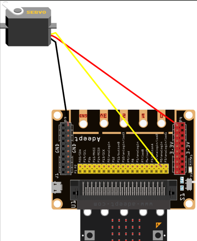
21.4 Circuit
You need to connect the components according to the following circuit diagram. You can use the “enlarge” function to view the picture.
21.5 MakeCode programming
Next, we will use the online MakeCode Editor to complete the experiment in this lesson.
21.5.1 Start programming
(1) Log in to the website
1. You need to enter the URL in the address bar of Google Browser:
https://makecode.microbit.org/
2. After the website is successfully opened, the interface as shown below will appear:

(2) Import a project
1. In the HOME interface, click the "Import" button to import the external ".hex" file:

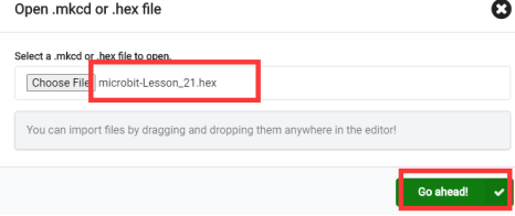
In the pop-up dialog box, select the "Import File", as shown in the following figure:

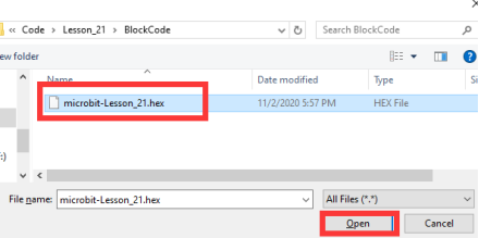
Click the "Choose File"

Find the code file for this lesson:
BBC _Microbit_Kit\Code\Lesson_21\BlockCode
Select the file in ".hex" format and click the Open:
2. Notice whether the file has been loaded into the following window, and then click the "Go ahead!" button, as shown in the following figure:
3.You can see the following interface when successfully opening the file:
21.5.2 Run the program
1. After the program is written, connect micro:bit and PC with a Micro USB cable.
2. After micro:bit is connected to the computer, you need to first "Pair device". Click the  button on the right of
  in the lower left corner, and then click the
  option, as shown in the following figure:

Then click  in the lower right corner

Then the following dialog box will pop up, select  , and then click

After the device is successfully paired, the  button changes to

3. Start to download the program to Micro:bit, and click the  button. Generally, the program will be downloaded directly to the Micro:bit. After the download is completed, your Micro:bit will restart and run the program just downloaded.Press the button A on the Micro:bit, and observe whether the motor rotates, as shown in the following figure:

[Note]
1.If the motor doesn’t rotate after the button A is pressed after the  is clicked, you need to click the
  button on the right of the
  , then click the
  and observe the Micro:bit again, as shown in the following figure:

2.If there is still no experimental phenomenon, you need to unplug and then plug in the USB cable connected to the Micro:bit, and then download the program again.
If you have problems, please send us an email: support@adeept.com
21.5.3 Learn the code program
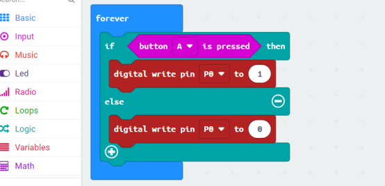
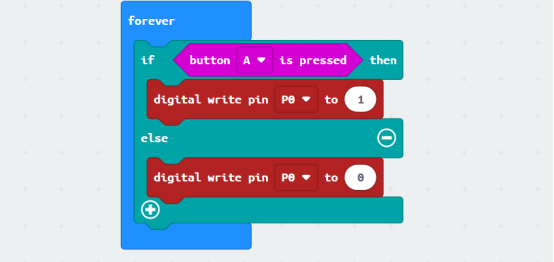
It is to determine whether the button A is pressed. If pressed, P0 outputs a high level, the relay is turned on,and the motor is running; if it is not pressed, P0 outputs a low level, and the motor does not run.
21.6 Python programming
21.6.1 Run the program
1.Connect micro:bit and PC with a Micro USB cable.
2. Open the Mu Editor installed on the computer, and click the button [Load] in the upper left corner to open the source code program of this lesson:

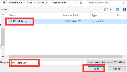
Find the code file for this lesson:
BBC _Microbit_Kit\Code\Lesson_21\PythonCode
Select the file in ".py" format and click the Open:
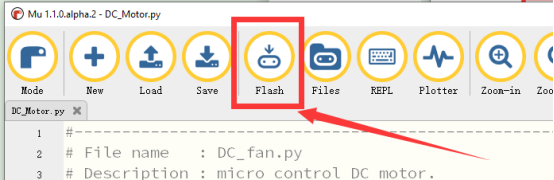
3. Click the [Flash] button to download the program to Micro:bit, as shown in the following figure:
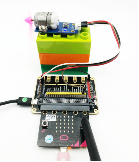
4.After the program is downloaded, observe whether the servo rotates, as shown in the following figure.
If you have problems, please send us an email: support@adeept.com
21.6.2 Learn the code program
(1)If A is pressed, P0 outputs a high level, the relay is turned on, and the motor is running.If it is not pressed, P0 outputs a low level, and the motor does not run.
3 4 5 6 7 | while True: if button_a.is_pressed(): pin0.write_digital(1) else: pin0.write_digital(0) |