In this lesson, we will carry out an interesting experiment by programming on the Micro:bit so as to read Potentiometer data.
31.1 Components to be prepared
31.2 Potentiometer
31.2.1 Potentiometer
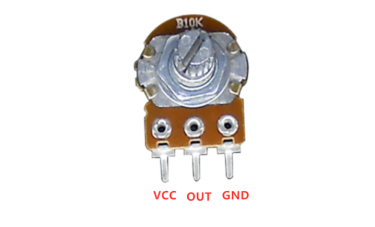
The potentiometer is a resistance element with three terminals and the resistance value can be adjusted according to a certain change law, which is equivalent to a variable resistor. Because its role in the circuit is to obtain a certain relationship with the input voltage (external voltage) to output Voltage, so called potentiometer. Potentiometers can be divided into rotary potentiometers, push-pull potentiometers, straight slide potentiometers, etc. according to the adjustment method. Our course experiment uses a rotary potentiometer.Its three pins are showed as below:
31.2.2 Working principle of potentiometer
The rotary potentiometer is an adjustable resistance element. It is composed of a resistor and a rotating system. When a voltage is applied between the two fixed contacts of the resistive body, the position of the contact on the resistive body is changed by the rotating system, and a voltage that has a certain relationship with the position of the moving contact can be achieved between the moving contact and the fixed contact. Potentiometer can be used to adjust the voltage and current.
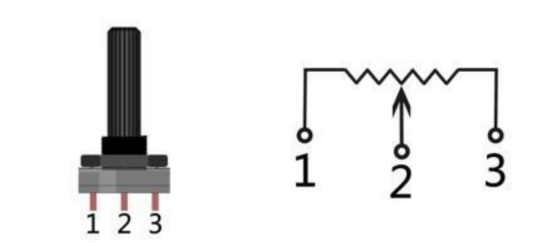
Our course uses a rotary potentiometer. Its structure is as shown in the figure below. By rotating the knob, the position of pin 2 is changed, thereby changing the resistance value from pin 2 to both ends. In the experiment. Connect pin 1 and pin 3 to the GND and 5V of the development board respectively. And then read the voltage divided by the pin 2 of the potentiometer through the analog input pin A0. The range is between 0V and 5V. The analog input function of Arduino has 10-bit precision, that is, it can convert the voltage signal of 0 to 5V into an integer form of 0 to 1024.
31.3 Low level and high level
In circuit, the form of binary (0 and 1) is presented as low level and high level.
Low level is generally equal to ground voltage (0V). High level is generally equal to the operating voltage of components.
The low level of Micro:bit is 0V and high level is 3.3V, as shown below. When IO port on Micro:bit outputs high level, low-power components can be directly driven,like LED.

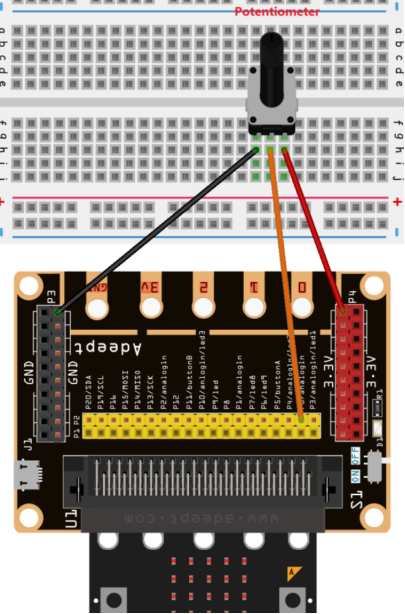
31.4 Circuit
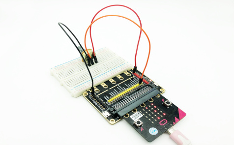
You need to connect the components according to the following circuit diagram. You can use the “enlarge” function to view the picture.
31.5 MakeCode programming
Next, we will use the online MakeCode Editor to complete the experiment in this lesson.
31.5.1 Start programming
(1) Log in to the website
1. You need to enter the URL in the address bar of Google Browser:
https://makecode.microbit.org/
2. After the website is successfully opened, the interface as shown below will appear:

(2) Import a project
1. In the HOME interface, click the "Import" button to import the external ".hex" file:

In the pop-up dialog box, select the "Import File", as shown in the following figure:

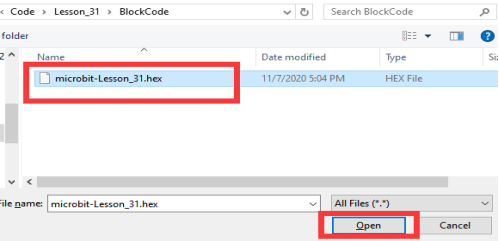
Click the "Choose File"

Find the code file for this lesson:
BBC_Microbit_kit\Code\Lesson_31\BlockCode
Select the file in ".hex" format and click the Open:
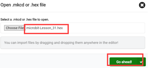
2. Notice whether the file has been loaded into the following window, and then click the "Go ahead!" button, as shown in the following figure:
3.You can see the following interface when successfully opening the file:
31.5.2 Run the program
1. After the program is written, connect micro:bit and PC with a Micro USB cable.
2. After micro:bit is connected to the computer, you need to first "Pair device". Click the  button on the right of
  in the lower left corner, and then click the
  option, as shown in the following figure:

Then click  in the lower right corner

Then the following dialog box will pop up, select  , and then click

After the device is successfully paired, the  button changes to

3. Start to download the program to Micro:bit, and click the  button. Generally, the program will be downloaded directly to the Micro:bit. After the download is completed, your Micro:bit will restart and run the program just downloaded. as shown below:
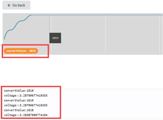
4.Then click the [Show console Device]:
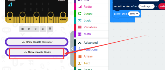
Rotating the potentiometer, you will see the output ADC value and voltage value.
[Note]:
1.If no experimental phenomenon has been detected after clicking the button  , you need to click the
  button on the right of the
  , and then click the
  , and observe the [Show console Device] again, as shown in the following figure:

2.If there is still no experimental phenomenon, you need to unplug and then plug in the USB cable connected to the Micro:bit, and then download the program again.
If you have problems, please send us an email: support@adeept.com
31.5.3 Learn the code program
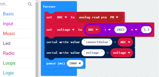
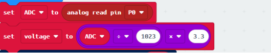
(1)Read the analog voltage value of the P0 pin, the range is 0-1023, and then convert the analog voltage value into a digital voltage value.
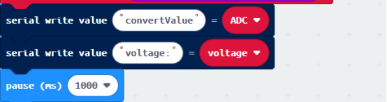
(2)Print the analog voltage and digital voltage of P0 pin every 1 second.
31.6 Python programming
31.6.1 Run the program
1.Connect micro:bit and PC with a Micro USB cable.
2. Open the Mu Editor installed on the computer, and click the button [Load] in the upper left corner to open the source code program of this lesson:

Find the code file for this lesson:
BBC_Microbit_Kit\Code\Lesson_31\PythonCode
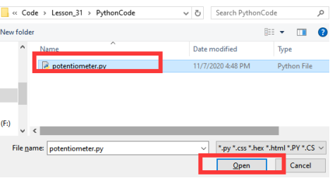
Select the file in ".py" format and click the Open:
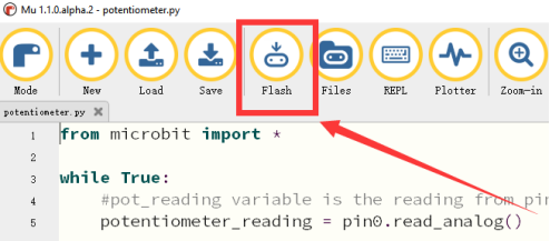
3. Click the [Flash] button to download the program to Micro:bit, as shown in the following figure:
4.After the program is downloaded, the number 1 will be displayed on the LED screen of the Micro:bit. Then you need to slowly rotate the potentiometer button. Every time you rotate, you will see the corresponding data on the LED screen of the Micro:bit, as shown in the following figure.

【Note】
If no data is displayed on the screen of the Micro:bit, check whether the wiring of the potentiometer is wrong or loose.
If you have problems, please send us an email: support@adeept.com
31.5.2 Learn the code program
The codes for this lesson are explained as follows.
(1)The data of the potentiometer can be read through the potentiometer_reading = pin0.read_analog(), and then the data will be displayed on the LED screen of the Micro:bit.
3 4 5 6 7 8 | while True:
potentiometer_reading = pin0.read_analog()
display.scroll(str(potentiometer_reading)) sleep(1000) |