In this lesson, we will carry out an interesting experiment to control a servo with a Micro:bit.
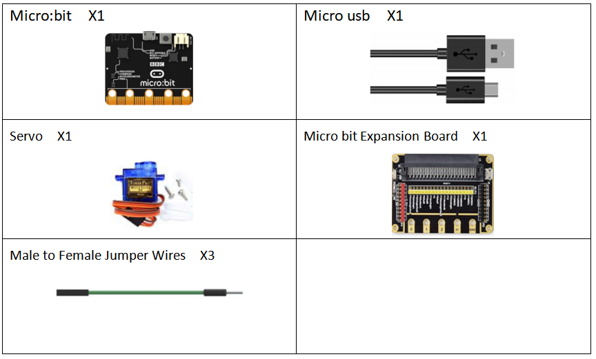
20.1 Components to be prepared
20.2 Servo
20.2.1 Servo
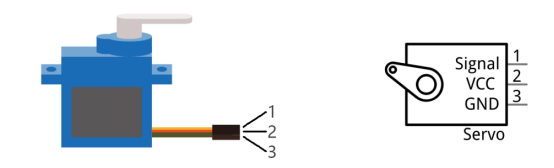
Servo is a compact package which consists of a DC Motor,a set of reduction gears to provide torque,a sensor and control circuit board.Most Servos only have a 180-degree range of motion via their“horn”.Servos can output higher torque than a simple DC Motor alone and they are widely used to control motion in model cars,model airplanes, robots,etc.Servos have three wire leads which usually terminate to a male or female 3-pin plug.Two leads are for electric power:Positive (2-VCC, Red wire),Negative (3-GND, Brown wire),and the signal line (1-Signal, Orange wire) as represented in the Servo provided in your Kit.
We will use a 50Hz PWM signal with a duty cycle in a certain range to drive the Servo. The lasting time 0.5ms-2.5ms of PWM single cycle high level corresponds to the Servo angle 0 degrees - 180 degree linearly. Part of the corresponding values are as follows:
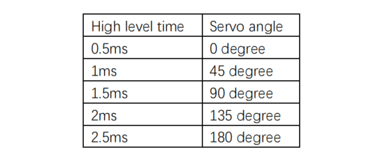
As can be seen from the above table, the servo rotates from 0 to 180 degrees, and the corresponding pulse width is 0.5-2.5ms. Then the analog voltage value is written to the micro:bit pin ranging from 25.6 to 128.
20.3 Low level and high level
In circuit, the form of binary (0 and 1) is presented as low level and high level.
Low level is generally equal to ground voltage (0V). High level is generally equal to the operating voltage of components.
The low level of Micro:bit is 0V and high level is 3.3V, as shown below. When IO port on Micro:bit outputs high level, low-power components can be directly driven,like LED.

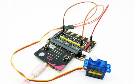
20.4 Circuit
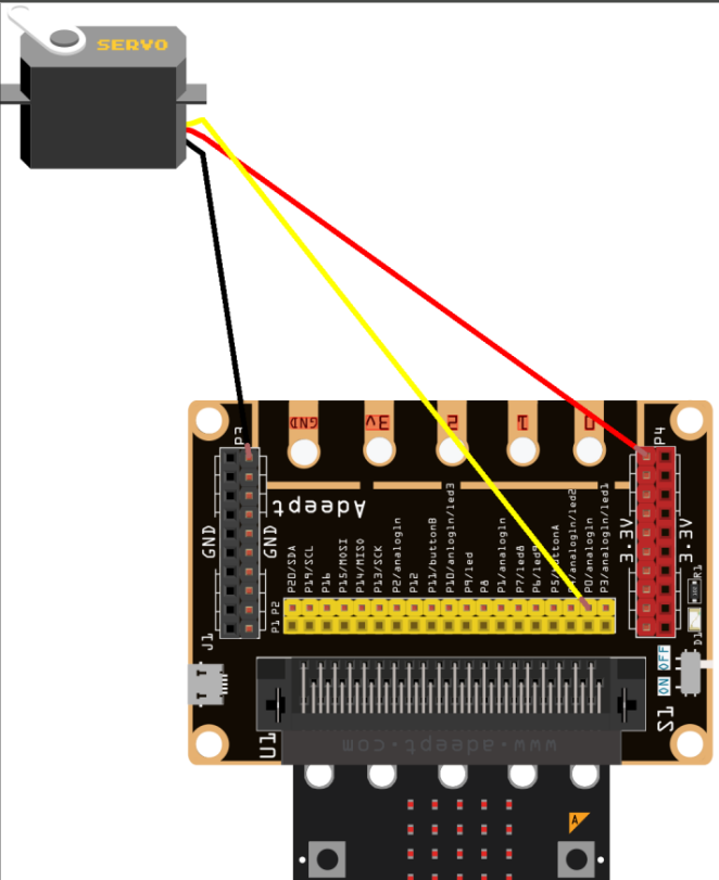
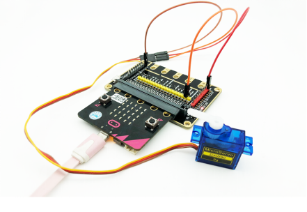
You need to connect the components according to the circuit diagram below. The 5V pin on the expansion board is connected to the "red wire" of the servo, the P0 pin is connected to the "orange" wire of the servo, and the GND is connected to the "brown" wire of the servo. You can use the “enlarge” function to view the picture.
20.5 MakeCode programming
Next, we will use the online MakeCode Editor to complete the experiment in this lesson.
20.5.1 Start programming
(1) Log in to the website
1. You need to enter the URL in the address bar of Google Browser:
https://makecode.microbit.org/
2. After the website is successfully opened, the interface as shown below will appear:

(2) Import a project
1. In the HOME interface, click the "Import" button to import the external ".hex" file:

In the pop-up dialog box, select the "Import File", as shown in the following figure:

Click the "Choose File"

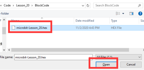
Find the code file for this lesson:
BBC _Microbit_Kit\Code\Lesson_20\BlockCode
Select the file in ".hex" format and click the Open:
2. Notice whether the file has been loaded into the following window, and then click the "Go ahead!" button, as shown in the following figure:
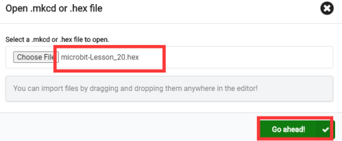
3.You can see the following interface when successfully opening the file:
20.5.2 Run the program
1. After the program is written, connect micro:bit and PC with a Micro USB cable.
2. After micro:bit is connected to the computer, you need to first "Pair device". Click the  button on the right of
  in the lower left corner, and then click the
  option, as shown in the following figure:

Then click  in the lower right corner

Then the following dialog box will pop up, select  , and then click

After the device is successfully paired, the  button changes to

3. Start to download the program to Micro:bit, and click the  button. Generally, the program will be downloaded directly to the Micro:bit. After the download is completed, your Micro:bit will restart and run the program just downloaded.Observe whether the servo rotates, as shown in the following figure:
[Note]
1.If the servo doesn’t rotate after the  is clicked, you need to click the
  button on the right of the
  , then click the
  and observe the Micro:bit again, as shown in the following figure:

2.If the servo still doesn’t rotate, you need to unplug and then plug in the USB cable connected to the Micro:bit, and then download the program again.
If you have problems, please send us an email: support@adeept.com
20.5.3 Learn the code program
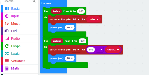
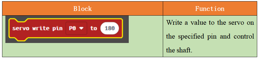
The following instruction blocks will be applied in the program. Please see the description of the function as follows:
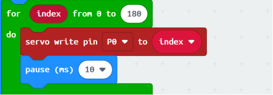
(1)In the for loop of 0-180, let the servo change from 0 to 180 degrees.
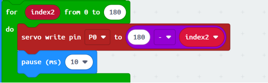
(2)In the for loop of 0-180, take the difference between 180 and index2, and let the servo rotate from 180 degrees to 0 degrees.
20.6 Python programming
20.6.1 Run the program
1.Connect micro:bit and PC with a Micro USB cable.
2. Open the Mu Editor installed on the computer, and click the button [Load] in the upper left corner to open the source code program of this lesson:

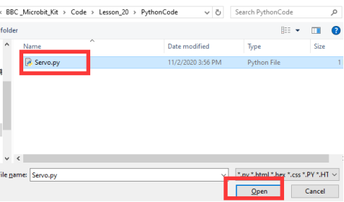
Find the code file for this lesson:
BBC _Microbit_Kit\Code\Lesson_20\PythonCode
Select the file in ".py" format and click the Open:
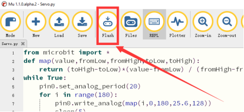
3. Click the [Flash] button to download the program to Micro:bit, as shown in the following figure:
4.After the program is downloaded, observe whether the servo rotates, as shown in the following figure.
If you have problems, please send us an email: support@adeept.com
20.6.2 Learn the code program
(1)Define map functions to convert values in one range to values in another range.
2 3 | def map(value,fromLow,fromHigh,toLow,toHigh): return (toHigh-toLow)*(value-fromLow) / (fromHigh-fromLow) + toLow |
(2)Set the interval of the PWM signal to 20ms. In a 0-180 for loop, convert the value in the range 0-180 to an analog voltage value in the range of 25.6~128, and then output the corresponding PWM signal to turn the servo from 0 degrees to 180 degrees.
4 5 6 7 8 | while True: pin0.set_analog_period(20) for i in range(180): pin0.write_analog(map(i,0,180,25.6,128)) sleep(5) |
(3)In a 180-0 for loop, convert the value in the range 0-180 to the analog voltage value in the range of 25.6~128,and then output the corresponding PWM signal to rotate the servo from 180 degrees to 0 degrees.
21 22 23 | for i in range(180,0,-1): pin0.write_analog(map(i,0,180,25.6,128)) sleep(5) |