In this lesson, we will carry out an interesting experiment to use a photoresistor to measure light intensity.
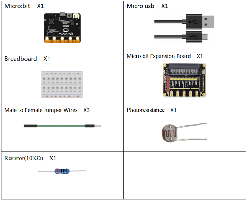
27.1 Components to be prepared
27.2 The introduction of Photoresistor
27.2.1 Photoresistor
A photoresistor is a light-controlled variable resistor. The resistance of a photoresistor decreases with the increasing incident light intensity; in other words, it exhibits photoconductivity. A photoresistor can be applied in light-sensitive detector circuits.
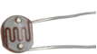
Photovaristor (photovaristor), also known as photoresistor, is a kind of resistor made by using the photoelectric effect of semiconductor to change the resistance value with the intensity of incident light;If the incident light is strong, the resistance decreases, and if the incident light is weak, the resistance increases. Photoresistors are generally used for light measurement, light control, and photoelectric conversion (converting changes in light into changes in electricity).
Photoresistors can be widely used in various light control circuits, such as the control and adjustment of lights, and can also be used in light control switches.
In dark, dark conditions, the resistance of the photoresistor is very high. The stronger the light, the smaller the resistance value. By measuring the voltage change value on both sides of the photoresistor, the change of the photoresistor value can be known and the light intensity value can be obtained. In the connection diagram,we can find a voltage divider connected in series with the photoresistor.
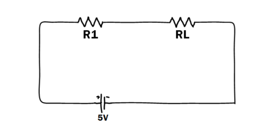
In the above figure, RL is the photoresistor, R1 is the voltage-dividing resistor in series, Vout=RLR1+RL∗VinVout=RLR1+RL∗Vin, in the dark, the resistance of RL will be very large, so Vout will be very Large, close to 5V. Once the light is irradiated, the value of RL will decrease rapidly, so Vout will decrease accordingly. It can be seen from the above formula that R1 should not be too small, preferably around 1k~10k, otherwise the ratio will not change significantly.
27.2.2 Experimental principle
In this experiment, we first conduct a relatively simple experiment of using a photoresistor. Since the photoresistor is a component that can change the resistance value according to the light intensity, naturally the analog port is also required to read the analog value. In this experiment, the PWM interface experiment can be used to replace the potentiometer with a photoresistor to realize the LED light when the light intensity is different. The brightness will also change accordingly.
A photoresistor is a light-controlled variable resistor. The resistance of a photoresistor decreases with the increasing incident light intensity; in other words, it exhibits photoconductivity. A photoresistor can be applied in light-sensitive detector circuits.
A photoresistor is made of a high resistance semiconductor. In the dark, a photoresistor can have a resistance as high as a few megohms (MΩ), while in the light, a photoresistor can have a resistance as low as a few hundred ohms. If incident light on a photoresistor exceeds a certain frequency, photons absorbed by the semiconductor give bound electrons enough energy to jump into the conduction band. The resulting free electrons (and their hole partners) conduct electricity, thereby lowering resistance. The resistance range and sensitivity of a photoresistor can substantially differ among dissimilar devices. Moreover, unique photoresistors may react substantially differently to photons within certain wavelength bands.
The schematic diagram of this experiment is shown below:
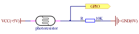
With the increase of the light intensity, the resistance of photoresistor will be decreased. The voltage of GPIO port in the above figure will become high.
27.3 Low level and high level
In circuit, the form of binary (0 and 1) is presented as low level and high level.
Low level is generally equal to ground voltage (0V). High level is generally equal to the operating voltage of components.
The low level of Micro:bit is 0V and high level is 3.3V, as shown below. When IO port on Micro:bit outputs high level, low-power components can be directly driven,like LED.

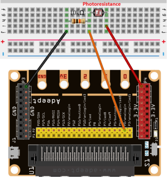
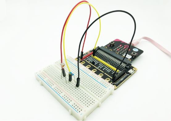
27.4 Circuit
You need to connect the components according to the circuit diagram below.
27.5 MakeCode programming
Next, we will use the online MakeCode Editor to complete the experiment in this lesson.
27.5.1 Start programming
(1) Log in to the website
1. You need to enter the URL in the address bar of Google Browser:
https://makecode.microbit.org/
2. After the website is successfully opened, the interface as shown below will appear:

(2) Import a project
1. In the HOME interface, click the "Import" button to import the external ".hex" file:

In the pop-up dialog box, select the "Import File", as shown in the following figure:

Click the "Choose File"

Find the code file for this lesson:
BBC_Microbit_Kit\Code\Lesson_27\BlockCode
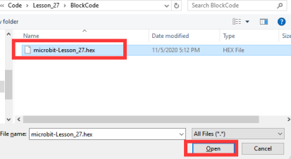
Select the file in ".hex" format and click the Open:
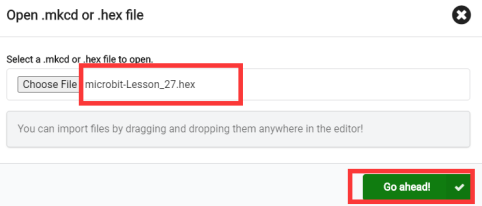
2. Notice whether the file has been loaded into the following window, and then click the "Go ahead!" button, as shown in the following figure:
3.You can see the following interface when successfully opening the file:

27.5.2 Run the program
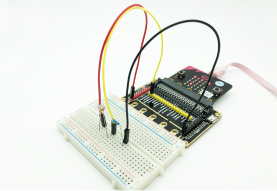
1. After the program is written, connect micro:bit and PC with a Micro USB cable.
2. After micro:bit is connected to the computer, you need to first "Pair device". Click the  button on the right of
  in the lower left corner, and then click the
  option, as shown in the following figure:

Then click  in the lower right corner

Then the following dialog box will pop up, select  , and then click

After the device is successfully paired, the  button changes to

3. Start to download the program to Micro:bit, and click the  button. Generally, the program will be downloaded directly to the Micro:bit. After the download is completed, your Micro:bit will restart and run the program just downloaded. The LED screen on the Micro:bit will show the light intensity detected by the photoresistor, as shown in the following figure:
[Note]
1.If the LED screen on the Micro:bit doesn’t show the light intensity after the  is clicked, you need to click the
  button on the right of the
  , and then click the
  , and observe the Micro:bit again, as shown in the following figure:

2.If the LED screen still doesn’t show the light intensity, you need to unplug and then plug in the USB cable connected to the Micro:bit, and then download the program again.
If you have problems, please send us an email: support@adeept.com
27.5.3 Learn the code program
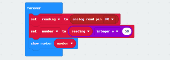
The following instruction blocks will be applied in the program. Please see the description of the function as follows:
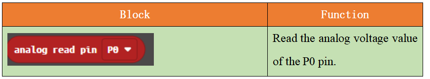
The data of the photoresistor connected to the P0 pin is read circularly, and then the read data is displayed on the LED screen of the Micro:bit.
27.6 Python programming
27.6.1 Run the program
1.Connect micro:bit and PC with a Micro USB cable.
2. Open the Mu Editor installed on the computer, and click the button [Load] in the upper left corner to open the source code program of this lesson:

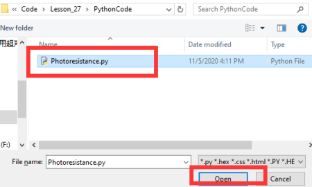
Find the code file for this lesson:
BBC_Microbit_Kit\Code\Lesson_27\PythonCode
Select the file in ".py" format and click the Open:
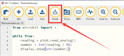
3. Click the [Flash] button to download the program to Micro:bit, as shown in the following figure:
4.After the program is downloaded, the LED screen of the Micro:bit will show the light intensity detected by the photoresistor, as shown in the following figure.
If you have problems, please send us an email: support@adeept.com
27.6.2 Learn the code program
The method of the read_analog() is used to read the light intensity data detected by the photoresistor. The method of the int(reading / 50) can convert the light intensity to an integer. The method of the display.show(str(number)) can display the data on the LED screen of the Micro:bit.
3 4 5 6 | while True: reading = pin0.read_analog() number = int(reading / 50) display.show(str(number)) |