In this lesson, we will learn how to control 180° Servo.
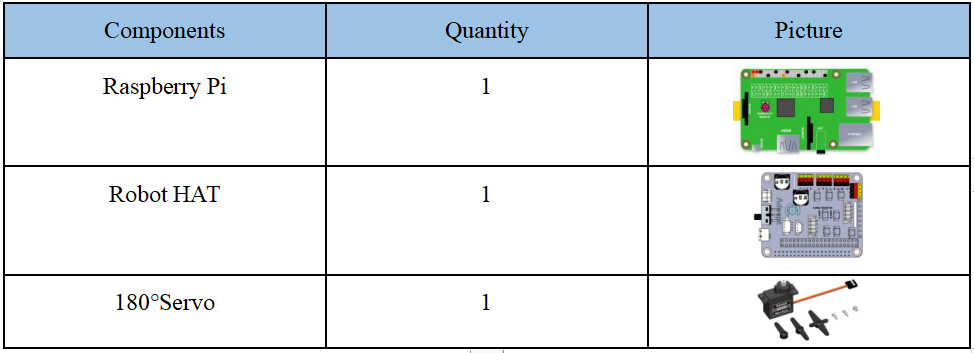
7.1 Components used in this course
7.2 Introduction of 180° Servo
What is a servo?
The servo is a position (angle) servo driver, which is suitable for those control systems that require constant angle changes and can be maintained. It has been widely used in high-end remote control toys, such as airplanes, submarine models, and remote control robots.
We use a 180° servo in this lesson, which can move between 0° and 180°. It is used in the RaspArm-S robot products. Since the 180° servo can use the PWM signal to control the rotation angle of a certain mechanism, it is a more commonly used module in robot products. The walking robot, robotic arm and pan/tilt are all driven by it.
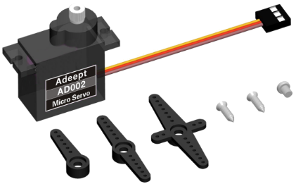
On the Raspberry Pi driver board Robot HAT, there is a PCA9685 chip specially used to control the servo. The Raspberry Pi uses I2C to communicate with the PCA9685. It controls the servo by sending pulse signals from the microcontroller. These pulses tell the servo mechanism of the servo where to move. The picture of the 180° servo is as follows:
If you do not use Robot HAT driver board to connect with Raspberry Pi driver board, then you need to connect Vin of OLED screen to 5V or 3.3V of Raspberry Pi, and connect GND of OLED screen to GND of Raspberry Pi. Connect SCL of Robot HAT to SCL of OLED, and SCA of Robot HAT to SCA of Raspberry Pi. Please refer to the pin definition diagram of Raspberry Pi for specific pins.
7.3 Wiring diagram (Circuit diagram)
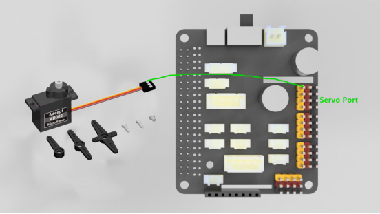
When the 180°Servo module is in use, it needs to be connected to the servo interface on the RobotHAT driver board. The yellow wire is connected to the yellow pin, the red wire is connected to the red pin, and the brown wire is connected to black pin,as shown below:
7.4 How to control 180°Servo
7.4.1Run theprogram of this course
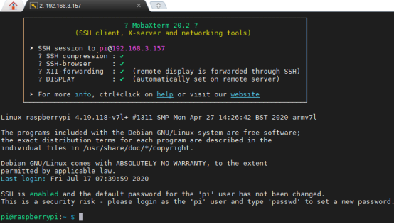
1. Open the terminal software MobaXterm:

2. Log in to your Raspberry Pi (the way to log in to Raspberry Pi has been introduced in Lesson 1):
3. The relevant code programs of the RaspArm-S robot are stored in the adeept_rasparms folder, which has been explained in "2.1 Downloading the code program for controlling the robot" in Lesson 2. First, you need to enter a command with the command window of the Raspberry Pi to enter the folder where the course code is stored: CourseCode, this folder stores the sample code program for each course, enter the following command:
cd adeept_rasparms/CourseCode

4. Enter the command to display the contents of the current directory:
ls

5. The 03Servo180 folder contains the sample code of this lesson. Enter the command to enter this folder:
cd 03Servo180

6. Enter the command to display the contents of the current directory:
ls

7. 180Servo_01.py is to control the servo to reciprocate; 180Servo_02.py is to control the servo to reciprocate slowly. When using the 180°Servo module, we need to install the Python dependency library which is needed to control the 180°Servo: Adafruit_PCA9685, and enter the following command in the console of the command window:
sudo pip3 install adafruit-pca9685

8.180Servo_01.py is a python program. You can run this program on the Raspberry Pi by directly typing the following commands:
sudo python3 180Servo_01.py

9. After successfully running the program, you will observe that the servo will rotate regularly.
10. If you want to terminate the running program, you can press the shortcut key Ctrl+C on the keyboard.
7.4.2 The main code program of this lesson
After the above hands-on practice, you already know how to use and run our course sample code program. Then you must be curious to know how our code program is programmed on the Raspberry Pi to control the 180° servo. Let's learn about the main code program together.Here we use Subline IDE to view and edit the code program of this lesson. For the specific method, please see the content of Lesson 2: "2.4 Editing the code program in the Raspberry Pi". In the file manager of the MobaXterm terminal, find adeept_rasparms/CourseCode /03Servo180, open the code for this lesson: 180Servo_01.py and 180Servo_02.py.
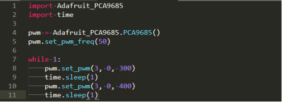
The code in the figure above is for the program 180Servo_01.py.In the above code, set_pwm_freq(50) is used to set the frequency of PWM to 50Hz. This setting depends on the model of the servo. The servo used by our robot products needs to be controlled by a 50Hz PWM signal. If you use other servos, we need to refer to the specific servo documentation to set this value.
pwm.set_pwm(3, 0, 300) is used to control the rotation of a servo to a certain position. 3 is the port number of the servo, which corresponds to the number marked on the RobotHAT drive board.Pay attention to the occasion that do not insert the ground wire, VCC and signal wire in the reverse direction when connecting the servo with the driver board. Brown to black, red to red, and yellow to yellow; 0 is the deviation value for controlling the rotation of the servo, but our program does not use this function to correct the deviation (the reason for the error of the servo can be referred to 4.2 precautions for structural assembly); 300 is the PWM duty cycle value to be set. Depending on the servo, the servo angle represented by this value is also different. The PWM duty cycle range of the servo we use is about 100 to 560, which corresponds to a rotation range of about 0° to 180°.
The above code cannot control the rotation speed of the servo. If we want a servo to slowly reciprocate between two positions, we need to use the method of increasing or decreasing the variable to control it.
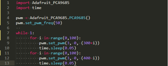
Using the above code can make the servo rotate slowly back and forth between 300 and 400, but this method of controlling the servo also has great drawbacks. When the program is executed to the slow motion part of the servo, it will be blocked, which will seriously affect the program. Therefore, a multi-threaded solution is provided in our robot product program to solve this problem.