In this lesson, we will learn the inverse solution function of the plane link.
19.1 Brief description
The plane linkage mechanism is a plane mechanism that composed of several components connected by a low pair (rotating pair, moving pair). The simplest plane linkage mechanism consists of four components, called plane four-bar mechanism. The plane linkage mechanism is widely used in various machinery, instruments and various electromechanical products.
The main advantages of the plane linkage mechanism are:
1) Since the kinematic pairs in the linkage mechanism are all low pairs of surface contact, they bear low pressure, which is convenient for lubrication, with lighter wear and high load-bearing capacity;
2) The shape of the component is simple, and it is convenient to add T. The contact between the components is maintained by the geometric constraints of the component itself, so the component works reliably;
3) It can realize the transformation between multiple sports forms:
4) The use of connecting rods can achieve a variety of motion trajectory requirements.
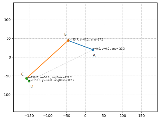
In our robotic arm, the plane connecting rod structure is also used. As shown in the figure below, ABCD constitutes a simple connecting rod, where the rotation of point A and point B is driven by the servo, and the connecting rod CD and the connecting rod BC are fixed right angle, the connecting rod CD is used to compensate the error of the end point of the connecting rod.
19.2 Learning the code program of the inverse function of the plane Link
Here we use Subline IDE to view and edit the code program of this course. For the specific method, please see "2.4 Editing the Code Program in Raspberry Pi" in Lesson 2.
In the file manager of the MobaXterm terminal, find adeept_rasparms/CourseCode, download the folder 07linkageRT to your PC, select this folder, click the button to download the file to the PC, save it in the path of English letters, and use Subline IDE to open the linkageRT.py in the 07linkageRT folder. The main code and comments are as follows:
Import the mathematical function library numpy.

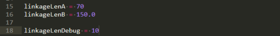
Set the length of AB to 70, the length of BC to 150.0, and the length of CD to 10.
servoNumCtrl = [0,1] is the number of the AB servos; servoDirection = [1,-1] corresponds to the movement direction of the AB servos, set by 1 and -1.

The array linkageLenCtrl which is composed of the lengths of links AB and BC.

The function planeLinkageReverse() is used to input the length of the link and the error parameters, the end position of the link and the number of the servos, and the rotation angle of the AB servos of this connecting rod mechanism can be obtained.

In the planeLinkageReverse() function, first calculate the incremental error, and use debugPos to correct the initial position error. Generally, debugPos is [0,0].

Used to calculate the angle error between the end point of the link and the rotation axis of the servo.

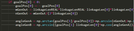
The input links AB, BC, and CD are abstracted into AB and BD to facilitate subsequent calculations.

Perform trigonometric calculations.
19.3 Running linkageRT.py on the PC
Find the folder 07linkageRT that you downloaded in step 19.2 on your PC, double-click to open the linkageRT.py program inside, you must make sure you have downloaded and installed Python according to "Lesson 4".
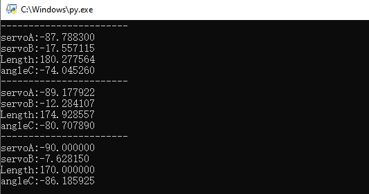
After double-clicking to open, as shown in the figure below, in the running command window, the printed data are the rotation angle of servo A; the rotation angle of servo B; the length of AD; the length of AD; the angle of AD.