In this lesson, we will learn how to assemble the RaspArm-S robotic arm. It has two forms of structure. The first form is a robotic arm that can grip objects. For the assembly tutorial, please refer to "10.2 RaspArm-S Robotic Arm Assembly Tutorial" in this lesson. "; The second form is a robotic arm that can be transformed into a "writing pen". For the assembly tutorial, please refer to "10.3 RaspArm-S Writing Pen Robotic Arm Assembly Tutorial" in this section of the course.
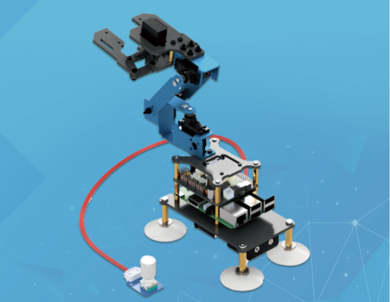
Before assembling, you need to prepare the parts used for assembling the RaspArm-S robot arm according to "10.1 Parts List".
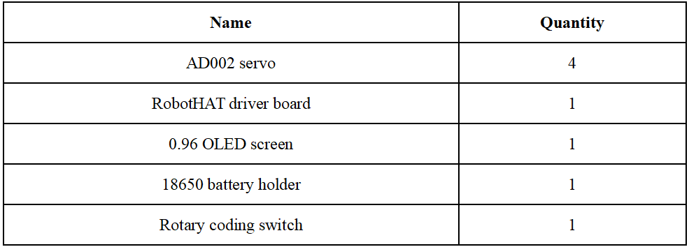
10.1 Parts list
Electrical parts:
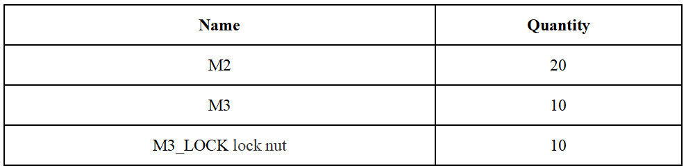
Copper pillar:
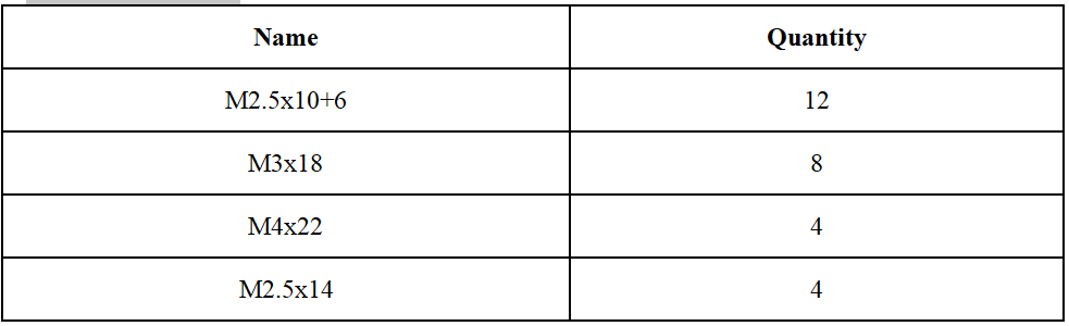
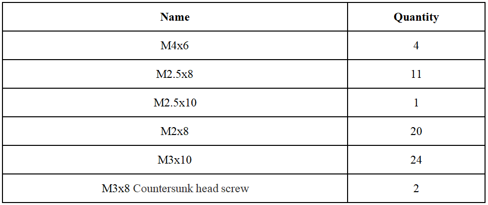
Screw:
Nut:
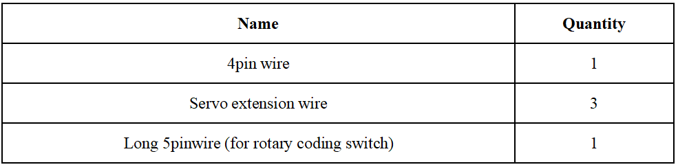
Wire:
Mechanical Parts:

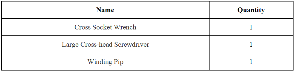
Tool:
Own parts:

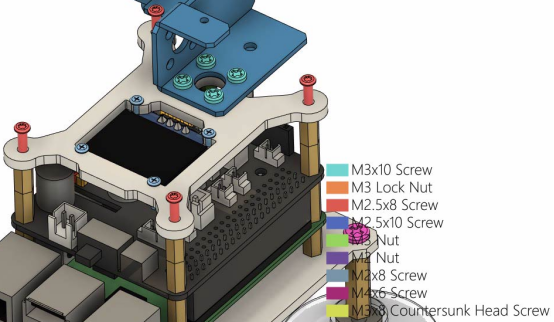
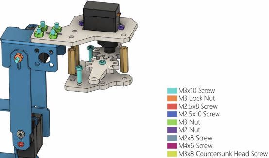
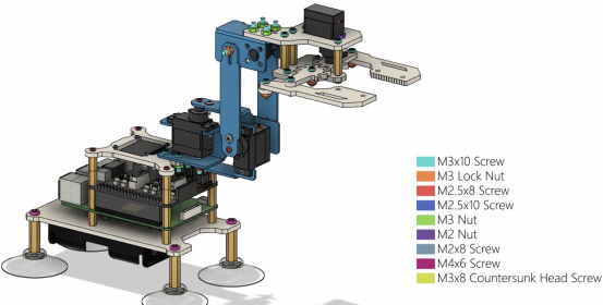
Screw color description:
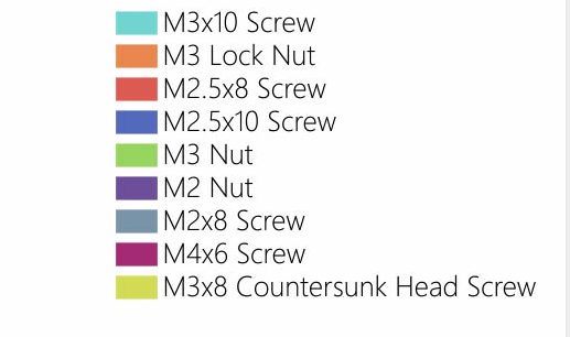
In order to make the structural assembly process more intuitive, we dye the screws used in the product. During the assembly process, you can refer to the color of the fastener in the tutorial to determine which type of screw and nut to use.
The actual color of the product is subject to the product, and the actual screws are not colored.
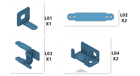
Names of aluminum alloy parts (the numbers in the figure are marked for the convenience of explaining the assembly)
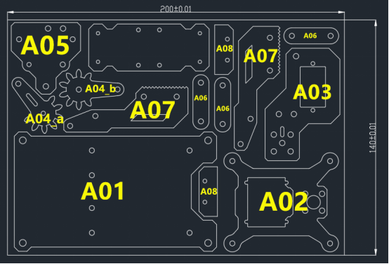
Acrylic part name (the number in the figure is for the convenience of explaining the assembly and marking)
10.2 RaspArms Robotic Arm Assembly Tutorial
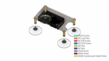
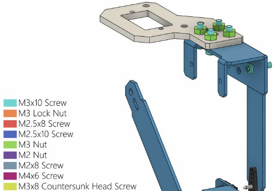
(1) Use 4 M4x6 Screws and 2 M3 Nuts to install on the acrylic part A01 as shown in the figure below.
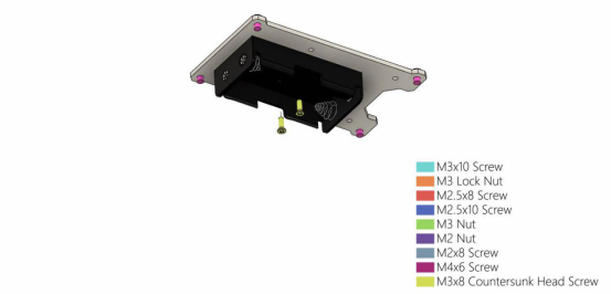
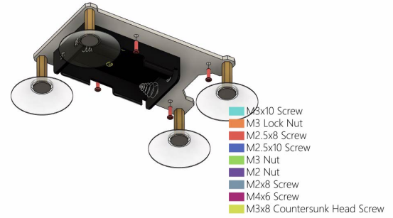
(2) Use 2 M3x8 Countersunk head screws to install the 18650 battery holder on the acrylic part A01.
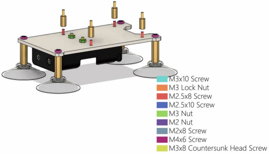
(3) Install 4 M4x22 Copper standoffs under the acrylic part A01.
Then install 4 sucker on the M4x22 Copper standoff.
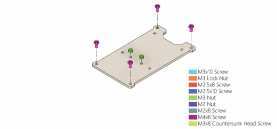
(4) Install 4 M2.5x8 Screws on the acrylic part A01.
Then install 4 M2.5x10+6 Copper standoffs on the M2.5x8 Screw.
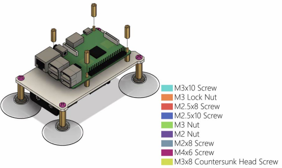
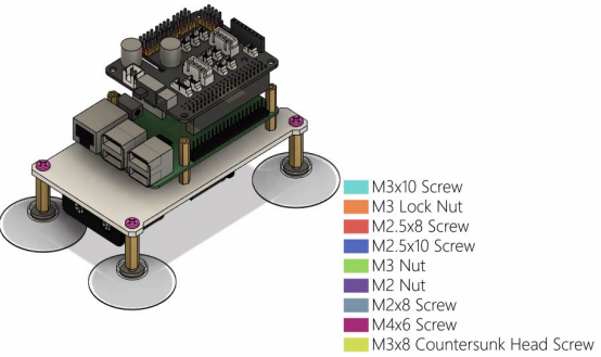
(5) Install the Raspberry Pi on the M2.5x10+6 Copper standoff;
Use 4 M2.5x14 Copper standoffs to fix on the Raspberry Pi.
(6) Install the RobotHAT driver board on the Raspberry Pi, and pay attention to the alignment of the GPIO pin ports.
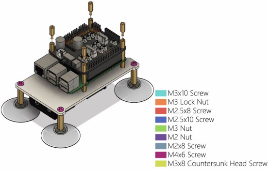
(7) Use 4 M2.5x10+6 Copper standoffs to fix RobotHAT driver board.
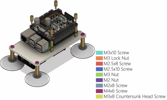
Then use 4 M2.5x10+6 Copper standoffs to connect and fix.
(8) First use 4 M2x8 Screws and 4 M2 nuts to fix the 0.96 OLED screen on the acrylic part A02. Note the orientation of the 0.96 OLED screen.
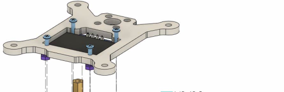
(9) Place the aluminum alloy part L04 on the acrylic part A02, the holes need to be aligned, and then use 4 M3x10 Screws and 4 M3 Nuts to fix L04.
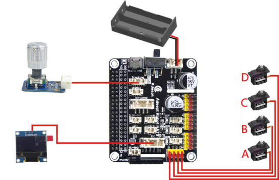
Wiring method:
When assembling to this step, you need to consider how to wire in advance.
First, you need to connect the external power cord to the Vin interface of the RobotHAT driver board;
Use the 5pin wire to connect the rotary encoder switch to the Track interface of the RobotHAT drive board;
Use a 4pin wire to connect the 0.96 OLED screen to the IIC interface of the RobotHAT driver board;
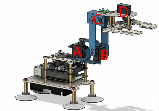
Connect the AD002 servo to the Servo interface. In our course example, the 4 servos are divided into A, B, C, D from bottom to top, and the 4 servos A, B, C, D are connected to Servo respectively on pins 12, 13, 14, and 15 of the interface, pay attention to the color alignment when wiring, otherwise the wiring will be reversed.
The figure below is the structure diagram of the servo of the robotic arm.
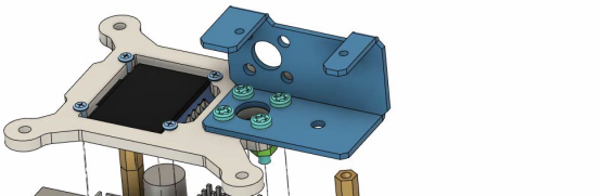
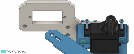
(10) Use 4 M2.5x8 Screws to install the assembled acrylic part A02 above the RobotHAT drive board.
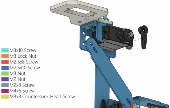
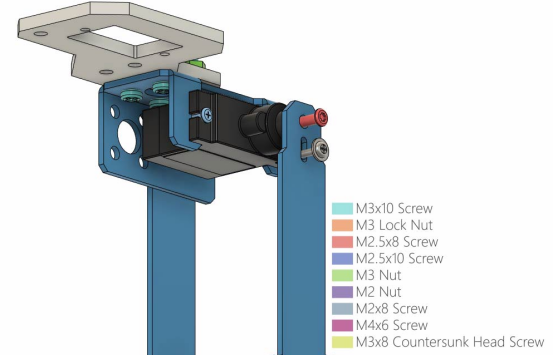
(11) Install the aluminum alloy part L03 on the aluminum alloy part L04, and fix it with 1 M3x10 Screws and 1 M3 Lock.
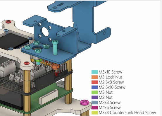
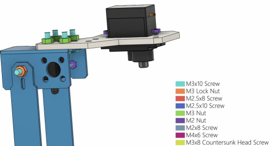
(12) Install AD002 servo on L03. The servo needs to be equipped with its own rocker arm. Use 2 M2x8 Screws and 2 M2 Nuts to fix the servo. The servo number of this part is A.
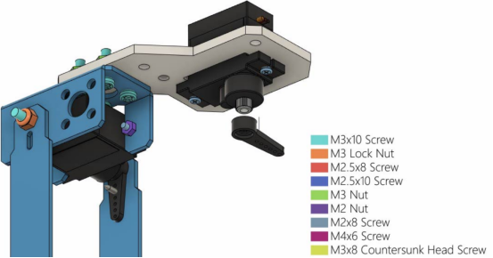
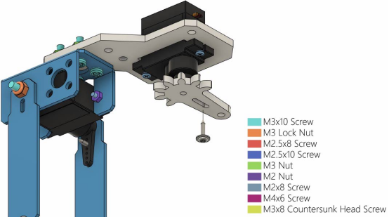
(13) Rotate L03 to the position as shown in the figure below, and use 1 M2.5x8 Screw and 1 M1.4x6 self-tapping screw that comes with the servo to fix L03.
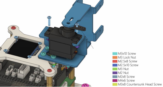
(14) Install the aluminum alloy part L02 on the L03, and use 1 M3x10 Screw and 1 M3 Lock Nut to fix L02.
(15) Install AD002 stervo on L03 as shown in the figure below, and fix AD002 servo with 2 M2x8 Screws and 2 M2 Nuts. The servo number for this part is B.
Then install the rocker arm that comes with the servo to the servo.
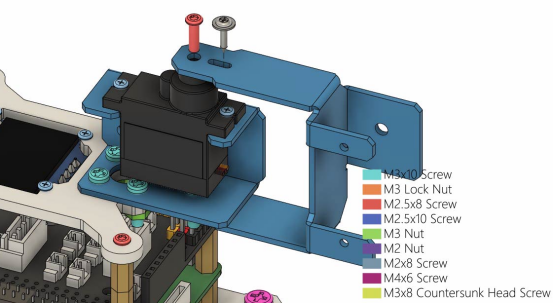
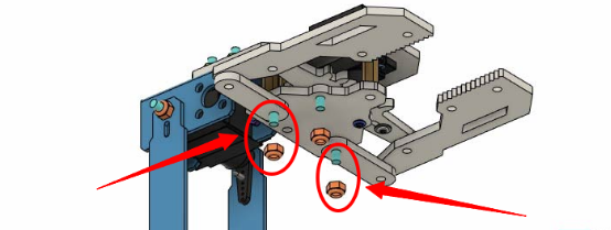
(16) Install another L02 on the position of the servo as shown in the figure below, and use 1 M2.5x8 Screw and 1 M1.4x6 self-tapping screw that comes with the servo to fix L02.
(17) Install another aluminum alloy part L04 on L02 as shown below, and fix L04 with 1 M3x10 Screw and 1 M3 Lock Nut.
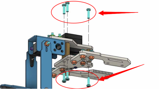
(18) Install the acrylic part A03 on L04 as shown in the figure below, and use 4 M3x10 Screws and 4 M3 Nuts to fix A03.
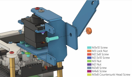
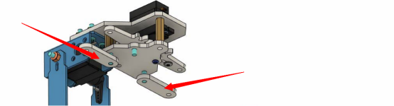
(19) Install AD002 servo on L04 as shown in the figure below, and install the servo rocker arm. The number of this part of the servo in the course is D3, which means the third servo of the robot arm from bottom to top. The servo number for this part is C.
Use 2 M2 Nuts to fix the servo.
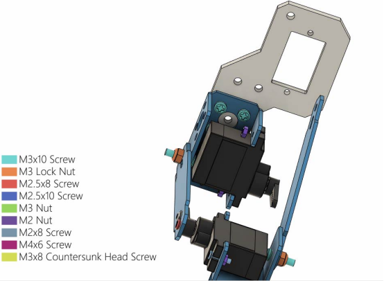
Then use 2 M2x8 Screws to fix the servo.
(20) Use 1 M2.5x8 Screw and 1 M1.4x6 self-tapping screw that comes with the servo to fix L02 on the servo.
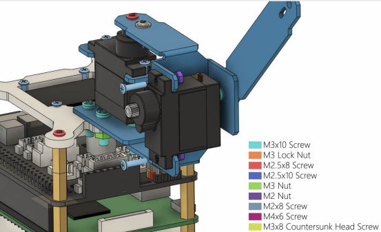
(21) Install AD002 servo on A03 as shown in the figure below, pay attention to the direction of the servo. You need to find 2 M2 Nuts to fix the servos. The servo number of this part is D.
Use 2 M2x8 Screws to fix the servo, and then install the rocker arm that comes with the servo.
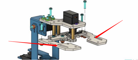
(22) Install the acrylic part A04_a on the rocker arm of the servo and fix it with a M1.4x6 self-tapping screw that comes with the servo.
(23) Use 1 M3x10 Screw to pierce another acrylic part A04_b, and place this A04_b and the A04_a connected to the servo on the same horizontal line; find 2 M3x10 Screws, 3 M3x18 Copper standoffs, and 1 Acrylic part A05. Place them as shown in the figure below. When assembling, first install and fix 3 M3x18 Copper standoffs on the 3 holes on the A03 of the servo, and use 3 M3x10 Screws to fix the M3x18 Copper standoff. Then install the A05 below on the M3x18 Copper standoff and fix it with 3 M3x10 Screws. Finally, put two M3x10 Screws into the corresponding holes, and then install A04_b on the same horizontal line as A04_a.
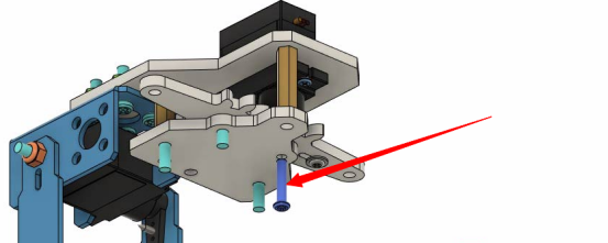
(24) Below A05, you need to use 1 M2.5x10 Screw to insert the hole connected with the servo, this screw needs to go through A04_a.
(25) Install two A06s below A05.
Use 3 M3 Lock Nuts to fix.
【Pay attention】:
The two M3 Lock Nuts used to fix A06 should not be installed too tightly, loosen them slightly. If they are too tight, the robot arm will not be able to grip things.
(26) Install two A07s on A06 and fix them with four M3x10 Screws and four M3 Lock Nuts.
(27) The final assembly is completed.
10.3 RaspArm-S writing pen robot arm assembly tutorial
If the shape and structure of the RaspArm-S robotic arm cannot satisfy your more creativity and ideas, then you can follow the assembly tutorial below to transform it into a "writing pen" shape robotic arm.
The RaspArm-S writing pen shape manipulator is modified from the shape and structure of the RaspArm-S manipulator arm, and its chuck is replaced with a structure that can be equipped with writing pens.
10.3.1 Assembling the robotic arm for the first time
If you did not perform the "10.2" steps to complete the robotic arm assembly, then you are assembling this robotic arm for the first time. For the first part of the assembly tutorial, please refer to (1)—(21) Steps in this lesson "10.2 RaspArm-S Robotic Arm Assembly Tutorial". At step (20), the robotic arm is assembled into the following form:
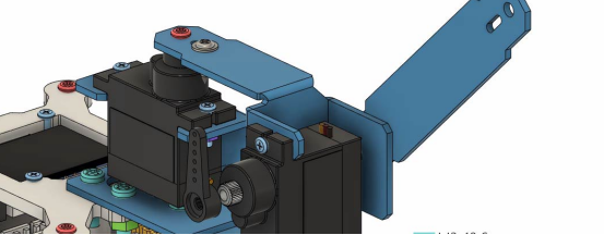
(22) You need to disassemble the A03 parts marked in the picture, as shown below:
(22) Then use 2 M3x10 Screws and 2 M3 Nuts to install the disassembled A03 (including the servo) to the side of L04, as shown below:

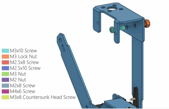
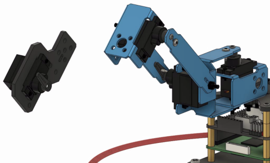
(23) Install the aluminum alloy part L01 on the D servo, and use 1 M2.5x8 Screw and 1 M1.4x6 self-tapping screw that comes with the servo to fix L01.

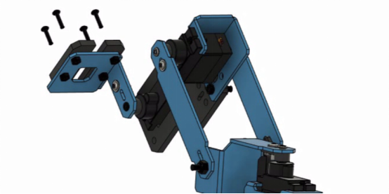
(24) Install 2 acrylic parts A08 on L01, pay attention to their placement direction, and fix them with 4 M2x8 Screws and 4 M2 nuts.
(25) After the final assembly is completed, you can use a rubber ring or rope to fix the pen. Then operate the writing pen robotic arm according to the following lesson case.

10.3.2 Basing on the robot arm to refit into a writing pen robot arm
If you have installed the robotic arm according to the steps in "10.2" of this lesson, how do you convert it into a pen robotic arm? Let's modify it together.
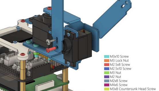
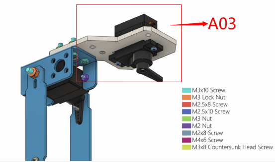
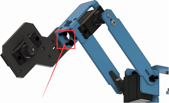
(1) First, the chuck part of the robotic arm needs to be disassembled, as the part in the red circle in the picture below, when disassembling, you need to keep the A03 part (do not disassemble the servo).
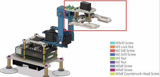
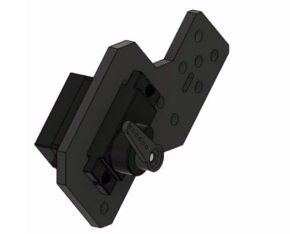
The structure part of A03 that has been disassembled is retained as shown below:
(2) Then use 2 M3x10 Screws and 2 M3 Nuts to install the disassembled A03 part (including the servo) to the side of L04, as shown in the following figure:
(3) Install the aluminum alloy part L01 on the D servo, and use 1 M2.5x8 Screw and 1 M1.4x6 self-tapping screw that comes with the servo to fix L01.
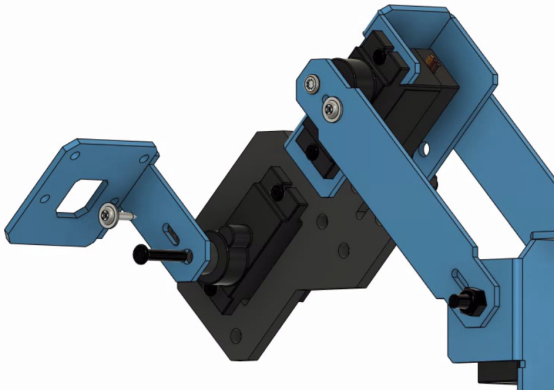
(4) Install the 2 acrylic parts A08 on L01, pay attention to their placement direction, and fix them with 4 M2x8 Screws and 4 M2 nuts.

(5) After the final assembly is completed, you can use a rubber ring or rope to fix the pen. Then operate the writing pen robotic arm according to the following lesson case.
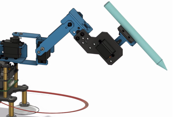
(6) For the use case of the morphological structure of the robotic arm writing pen, please refer to the content of lesson 14 below.