In this lesson, we will give some introduction to BBC micro bit. For more information about BBC micro bit, please log on to the official website to learn:
https://microbit.org/get-started/user-guide/overview/
1.1 BBC micro bit
The Micro Bit (also referred to as BBC Micro Bit, stylized as micro:bit) is an open source hardware ARM-based embedded system designed by the BBC for use in computer education in the UK. It was first announced on the launch of BBC's Make It Digital campaign on 12 March 2015 with the intent of delivering 1 million devices to pupils in the UK. The final device design and features were unveiled on 6 July 2015 whereas actual delivery of devices, after some delay, began in February 2016.
The device is described as half the size of a credit card and has an ARM Cortex-M0 processor, accelerometer and magnetometer sensors, Bluetooth and USB connectivity, a display consisting of 25 LEDs, two programmable buttons, and can be powered by either USB or an external battery pack.The device inputs and outputs are through five ring connectors that form part of a larger 25-pin edge connector.
Details of the latest micro:bit hardware revision:
https://tech.microbit.org/hardware/
1.2 BBC micro:bit features
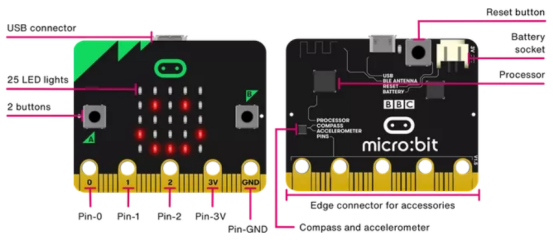
Your BBC micro:bit has a wide range of features for you to explore. Find out more about each of the numbered features below.
【FRONT】
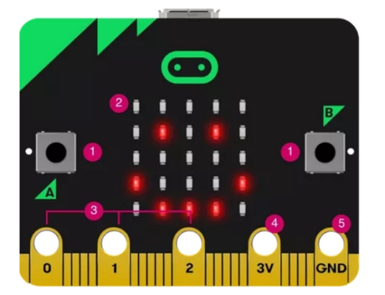
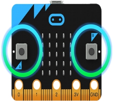
【1】Buttons
There are two buttons on the front of the micro: bit (labelled A and B). You can detect when these buttons are pressed, allowing you to trigger code on the device.
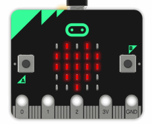
【2】LEDs
An LED, or light-emitting diode is an output device that gives off light. Your BBC micro:bit has a display of 25 LEDs for you to program.
25 LEDs arranged in a 5x5 grid make up the display for showing pictures, words and numbers. They can also act as sensors, measuring how much light is falling on your micro:bit.
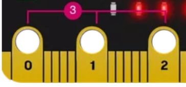
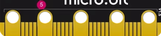
【3】Pin-GPIO
On the bottom edge of your BBC micro:bit there are 25 gold strips, called pins. These pins allow you to really get creative. You can create circuits, connect external things like buzzers and motors and make your own fun projects.
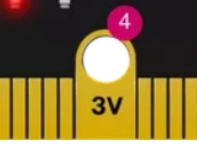
【4】Pin-3 volt power
You can power external LEDs and other electronics using the 3 volt power pin.
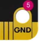
【5】Pin-Ground
The GND pin is the ground or Earth pin - it's used to complete electrical circuits when you connect headphones, LEDs or external switches to your micro:bit.
【Back】
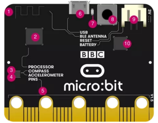
【1】Radio&Bluetooth antenna
Your micro:bit can communicate with other micro:bits by radio, and with other devices using Bluetooth.
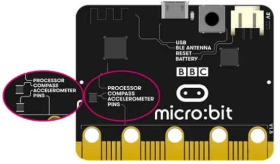
【2】Processor&temperature sensor
The micro:bit's processor is its brain, fetching, decoding and carrying out your instructions. It also contains a temperature sensor so you can measure how warm your environment is.

【3】compass
A digital compass is an input sensor that detects magnetic fields. Your BBC micro:bit has an inbuilt compass that can detect the direction in which it is facing.Find magnetic North or measure the strength of magnetic fields using the micro:bit's compass.
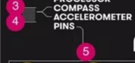
【4】Accelerometer
An accelerometer is a motion sensor that measures movement. The accelerometer in your BBC micro:bit detects when you tilt it left to right, backwards and forwards and up and down.Measure gestures and forces in 3 dimensions.

【5】Pins
On the bottom edge of your BBC micro:bit there are 25 gold strips, called pins. These pins allow you to really get creative. You can create circuits, connect external things like buzzers and motors and make your own fun projects.
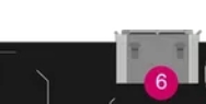
【6】Micro USB socket
The USB interface allows you to connect the micro: bit to your computer via a micro-USB cable, which will power the device and allow you to download programs onto the micro: bit.
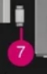
【7】Single LED
The single LED on the back of your micro:bit flashes when you are downloading a program to it, and lights to show it's being powered from the USB socket.
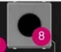
【8】Reset button
Restart your micro:bit programs with the reset button
【9】Battery socket
Instead of powering your micro:bit from the USB socket, you can unplug it from your computer and use a battery pack instead. This is really useful if you want to take your micro:bit outside, wear it or play games with it. It can run for ages off two AAA batteries.

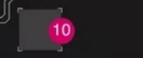
【10】USB interface chip
The interface chip handles the USB connection, and is used for flashing new code to the micro:bit, sending and receiving serial data back and forth to your computer.
1.3 Hardware specifications
Review the BBC micro:bit hardware specifications in detail on the micro:bit developer community website:
https://tech.microbit.org/hardware/
micro:bit board versions
There are two different versions of the micro:bit board. Newer micro:bits have a combined compass and accelerometer chip and on the older ones they are separate. Both versions work in exactly the same way.
1.4 GPIO
The micro:bit has 25 edge connectors for external connection boards, which we call "pins". The edge connectors are the gray area on the right side of the picture above. There are five large pins that are also connected to the holes on the board labeled 0,1,2,3V and GND. And along the same edge, there are 20 small plugs that can be used when plugging a BBC micro:bit into the edge connector.
The following is the GPIO serial number and function diagram of micro:bit:
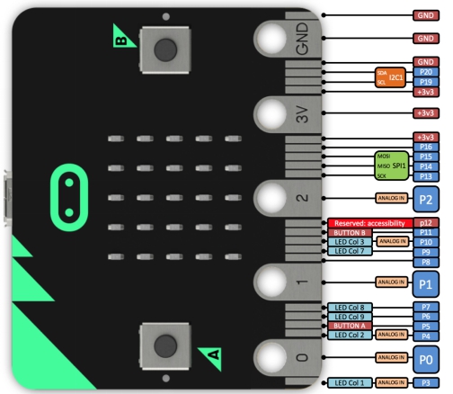
For more information about PIns, please refer to the link below:
https://tech.microbit.org/hardware/edgeconnector/
Among Micro:bit pins, the pin functions are classified as shown in the following table:
GPIO | P0,P1,P2,P3,P4,P5,P6,P7,P8,P9,P10,P11,P12,P13,P14,P15,P16,P19,P20 |
ADC/DAC | P0,P1,P2,P3,P4,P10 |
IIC | P19(SCL),P20(SDA) |
SPI | P13(SCK),P14(MISO),P15(MOSI) |
PWM | P0,P1,P2,P3,P4,P10 |
occupied | P3(LED Col1),P4(LED Col2), P5(BUTTON A),P6(LED Col9), P7(LED Col8),P9(LED Col7), P10(LED Col3),P11(Button B), |
【Large pin】:
You can easily connect alligator clips or 4mm banana plugs to the five large pins.
The first three pins labeled 0, 1, and 2 are flexible, and they are often referred to as "General Purpose Input and Output" (abbreviated as GPIO). The three pins 0, 1 and 2 can also be called analog-to-digital converter (ADC) to read the analog voltage, they all have the same function:
0:GPIO (general purpose digital input and output) with analog-to-digital converter (ADC).
1:GPIO with ADC
2:GPIO with ADC
The other two big pins (3V and GND) are very different!
【pay attention】:
The pins marked as 3V and GND are related to the power supply of the circuit board and must not be connected together.
power input:
If the BBC micro:bit is powered by USB or battery, you can use the 3V pin as a power output to power peripherals.
3V:
3 volt power output or power input.
(1) Power output: If the BBC micro:bit is powered by USB or battery, you can use the 3V pin as the power output to power the peripherals;
(2) Power input: If the BBC micro:bit is not powered by USB or battery, you can use the 3V pin as the power input to power the BBC micro:bit
GND:
Ground to complete the circuit (required when using the 3V pin)
If you hold the "GND" pin with one hand, you can program the BBC microbit to detect whether you have touched 0, 1, or 2 pins with the other hand, providing you with three more buttons for you to proceed Experiment (you just use your body to complete the circuit).
【Small pin】:
There are 20 small pins numbered sequentially from 3 to 22 (these pins are not marked on the BBC micro:bit, they are marked in the picture above).
These small pins are different from the three large pins dedicated to external connections. Some small pins are shared with other components on the BBC micro:bit board. For example, pin P3 is shared with some LEDs on the BBC micro:bit screen, so if you use the screen to scroll messages, you cannot use this pin.
Pin P3:
GPIO is shared with LED Col 1 of the LED screen; when the LED screen is off, this pin can be used for ADC and digital I/O.
Pin P4:
GPIO is shared with LED Col 2 of the LED screen; when the LED screen is off, this pin can be used for ADC and digital I/O.
Pin P5:
GPIO is shared with button A.This allows you to trigger or detect the external click of button "A". This pin has a pull-up resistor, which means its voltage is 3V by default. To replace button A on the BBC micro:bit with an external button, connect one end of the external button to pin 5 and the other end to GND. When the button is pressed, the voltage on pin 5 is pulled down to 0, which generates a button click event.
Pin P6:
GPIO is shared with the LED Col 9 of the LED screen; it can be used for digital I/O when the LED screen is off.
Pin P7:
GPIO is shared with the LED Col 8 of the LED screen; it can be used for digital I/O when the LED screen is off.
Pin P8:
Dedicated GPIO, used to send and detect digital signals.
Pin P9:
GPIO is shared with the LED Col 7 of the LED screen; it can be used for digital I/O when the LED screen is off.
Pin P10:
GPIO is shared with the LED Col 3 of the LED screen; when the LED screen is off, it can be used for ADC and digital I/O.
Pin P11:
GPIO shared with button B. This allows you to trigger or detect the external click of button "B".
Pin P12:
Dedicated GPIO, used to send and detect digital signals.
Pin P13:
The GPIO is traditionally used for the serial clock (SCK) signal of the 3-wire serial peripheral interface (SPI) bus.
Pin P14:
It is usually used for the GPIO of the MISO signal of the SPI bus.
Pin P15:
Usually used for the GPIO of the SPI bus's master output slave input (MOSI) signal.
Pin P16:
Dedicated GPIO (usually also used for SPI chip selection function).
Pin P17 and P18:
These pins are connected to a 3V power supply.
Pin P19 and P20:
Realize the clock signal (SCL) and data line (SDA) of the I2C bus communication protocol. Through I2C, several devices can be connected on the same bus, and can send messages to or read messages from the CPU. Internally, the accelerometer and compass are connected to i2c.
Pin P21 and P22:
These pins are connected to the GND pin and have no other functions.