In this lesson, we will carry out an interesting experiment on how to read the data of water level sensor module.
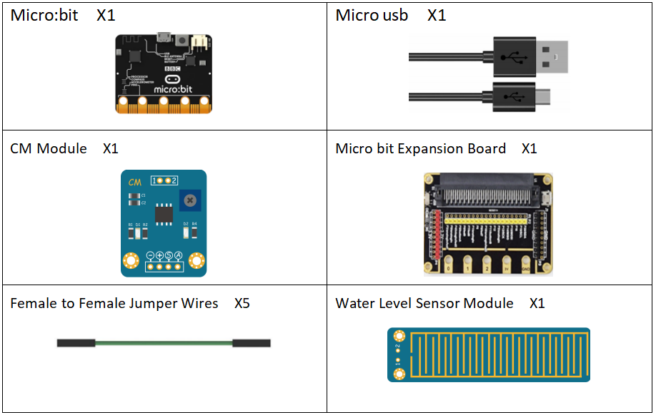
42.1 Components to be prepared
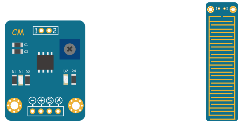
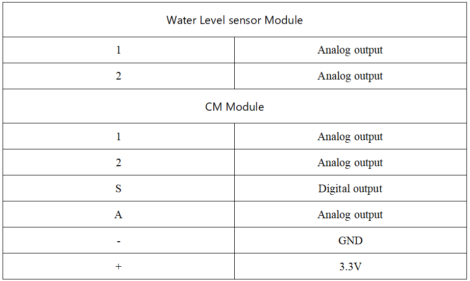
42.2 CM and Water level sensor module
42.2.1 CM and Water level sensor module
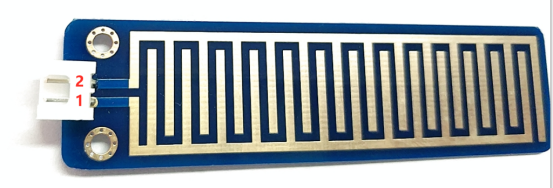
The module is a simple water level sensor. It measures the water volume by the printed wires exposed to the air on the module. The more water on the surface, more wires connected. Thus, the area of electrified wires gets larger, so the output voltage will increase.Easily complete the conversion of water volume to analog signal, and the output analog value can be directly read by the Micro:bit development board to achieve the effect of water level alarm.The surface of the sensor is gilded to prolong its life.
42.3 Low level and high level
In circuit, the form of binary (0 and 1) is presented as low level and high level.
Low level is generally equal to ground voltage (0V). High level is generally equal to the operating voltage of components.
The low level of Micro:bit is 0V and high level is 3.3V, as shown below. When IO port on Micro:bit outputs high level, low-power components can be directly driven,like LED.

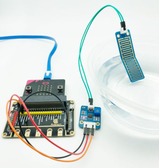
42.4 Circuit
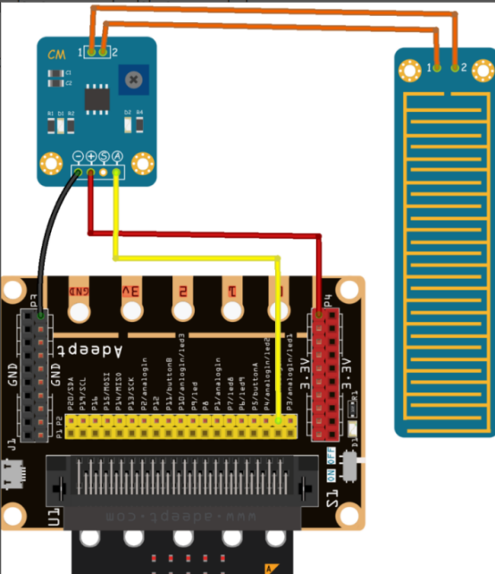
You should connect the components according to the following circuit diagram, and view the pictures with the function “Zoom in”:
42.5 MakeCode programming
In the following part, we will make use of the online MakeCode editor to complete the experiment in this lesson.
42.5.1 Start programming
(1) Log in to the website
1. You need to enter the URL in the address bar of Google Browser:
https://makecode.microbit.org/
2. After the website is successfully opened, the interface as shown below will appear:

(2) Import a project
1. In the HOME interface, click the "Import" button to import the external ".hex" file:

In the pop-up dialog box, select the "Import File", as shown in the following figure:

Click the "Choose File"

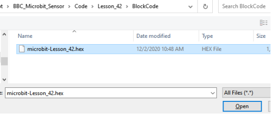
Find the code file for this lesson:
BBC_Microbit_Sensor\Code\Lesson_42\BlockCode
Select the file in ".hex" format and click the Open:
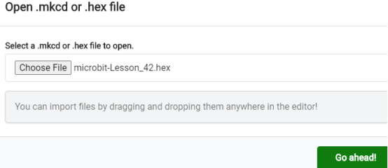
2. Notice whether the file has been loaded into the following window, and then click the "Go ahead!" button, as shown in the following figure:
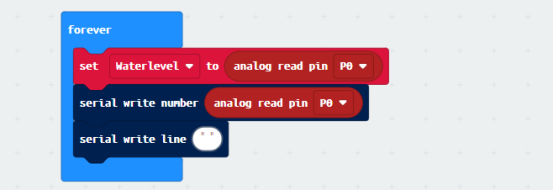
3.You can see the following interface when successfully opening the file:
42.5.2 Run the program
1. After the program is written, connect micro:bit and PC with a Micro USB cable.
2. After micro:bit is connected to the computer, you need to first "Pair device". Click the  button on the right of
  in the lower left corner, and then click the
  option, as shown in the following figure:

Then click  in the lower right corner

Then the following dialog box will pop up, select  , and then click

After the device is successfully paired, the  button changes to

3. Start to download the program to the Micro:bit, click the button  , and the program will be downloaded directly to the Micro:bit. Then wait for the download completion. When the download is successful, your Micro:bit will restart and run the program you have downloaded before.
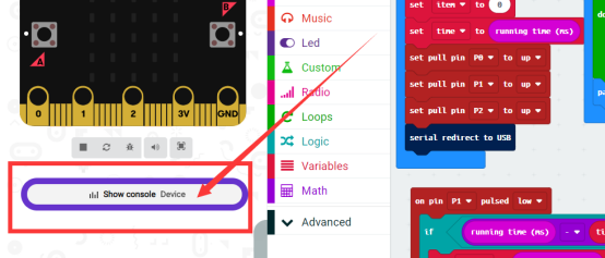
4.Then click the button【Show Console Device】on the left, as shown below:
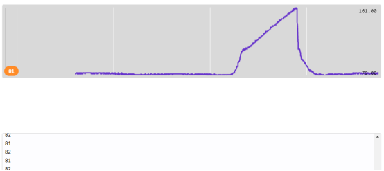
5.Then you will see the waveform below. Place Water Level Sensor Module into the water slowly and observe the changes in the waveform.
[Note]
1.If no experimental phenomenon has been detected after clicking the button  , you need to click the
  button on the right of the
  , and then click the
  , as shown in the following figure:

2. If no experimental phenomenon is observed, you should check whether the USB cable of Micro:bit is successfully connected. If not, please download the program again.
3.Water on the surface of The Water Level Sensor Module will affect the output value of the analog pin.
If you have problems, please send us an email: support@adeept.com
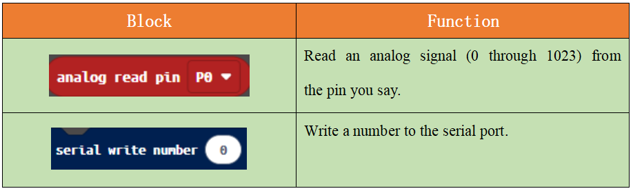
42.5.3 Learn the code program
The following instruction blocks will be applied in the program. Please see the description of the function as follows:
42.6 Python programming
42.6.1 Run the program
1.Connect micro:bit and PC with a Micro USB cable.
2. Open the Mu Editor installed on the computer, and click the button [Load] in the upper left corner to open the source code program of this lesson:

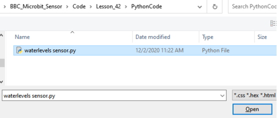
Find the code file for this lesson:
BBC_Microbit_Sensor\Code\Lesson_42\PythonCode
Select the file in ".py" format and click the Open:
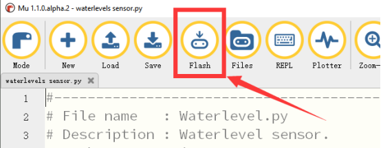
3.Click the button 【Flash】to download the program to Micro:bit. Click the button  immediately, and the output data can be read on the console, as shown below:
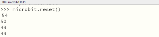
4.Please place Water Level Sensor Module into the water slowly, and there will be some changes of the data output on the console, as shown below:

【Note】
1. If no data can be read on the console,click button【Flash】for a second time, and click the button  immediately. If no data have been output yet, please repeat the above steps or check whether the wiring is connected correctly.
If you have problems, please send us an email: support@adeept.com
42.6.2 Learn the code program
The following is an explanation of the course code of this section.
(1)Read the data of Water Level Sensor Module and print out the data.
11 12 13 14 15 | while True: # define potentiometer pin waterlevel = pin0.read_analog() print(waterlevel) sleep(1000) |