In this lesson, we will carry out an interesting experiment to make a compass with the Micro:bit.
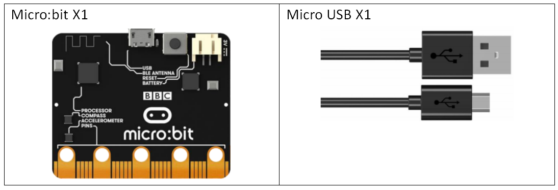
12.1 Components to be prepared
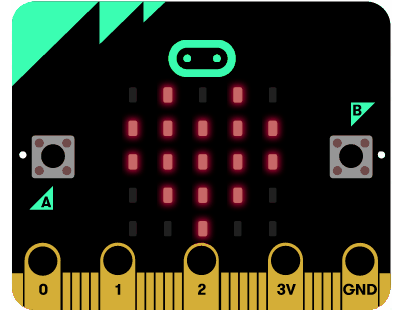
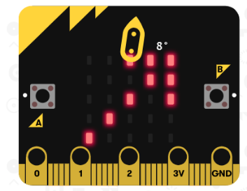
12.2 LED display
The front LED display of Micro:bit consists of 25 5x5 lattice LEDs.
25 LEDs arranged in a 5x5 grid make up the display for showing pictures, words and numbers.
12.3 Compass
(1)A digital compass is an input sensor that detects magnetic fields. Your BBC micro:bit has an inbuilt compass that can detect the direction in which it is facing. Find magnetic North or measure the strength of magnetic fields using the micro:bit's compass.
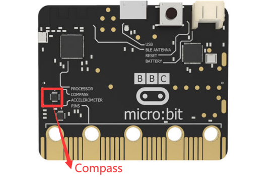
(2)A digital compass is an input sensor that detects magnetic fields. Your BBC micro:bit has an inbuilt compass that can detect the direction in which it is facing.
Watch the video to find out more, then choose a project to start using your micro:bit as a compass.
https://microbit.org/get-started/user-guide/features-in-depth/#compass
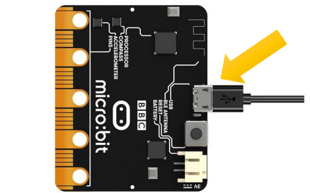
12.4 Circuit
Connect micro:bit and PC with a Micro USB cable.
12.5 How it works and calibrate the compass
1.Your micro:bit has a compass sensor called a magnetometer that measures magnetic fields. It can sense the Earth's magnetic field and so you can use it as a compass.
2.When you first use the micro:bit compass you have to calibrate it. A little game appears on the screen where you have to tilt the micro:bit to light up every LED, then you’re ready to go.
If this is the first time you have used an Micro:bit magnetic field sensor, the pattern of the LED matrix will be the“TILT TO FILL SCREEN”.
For the way to calibrate a Micro:bit electronic compass, please click the following link to view the video.
[Note]
Also, because the magnetometer is sensitive to magnetic fields, you should avoid attaching the micro:bit to any metal objects or rest it on a metal table, as this will affect both the calibration and the accuracy of the reading in normal use.
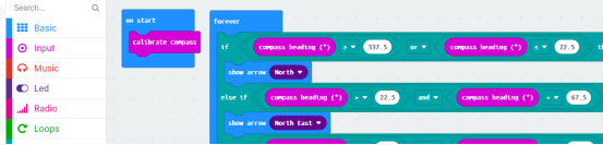
3.The program uses an infinite (forever) loop to keep taking compass readings and it stores them in a variable called ‘bearing’. It then uses selection: an if… else statement to show N for North on the LED display if the bearing is greater (>) than 337.5 degrees or less than (<)22.5. This means that it will show you where North is as long as your micro:bit is pointing in roughly the right direction.

12.6 MakeCode programming
We will use an online MakeCode Editor to complete the experiment in this lesson, as shown below.
12.6.1 Start programming
(1) Log in to the website
1. You need to enter the URL in the address bar of Google Browser:
https://makecode.microbit.org/
2. After the website is successfully opened, the interface as shown below will appear:

(2) Import a project
1. In the HOME interface, click the "Import" button to import the external ".hex" file:

In the pop-up dialog box, select the "Import File", as shown in the following figure:

Click the "Choose File":

Find the code file for this lesson:
BBC_Microbit_Sensor\Code\Lesson_12\BlockCode
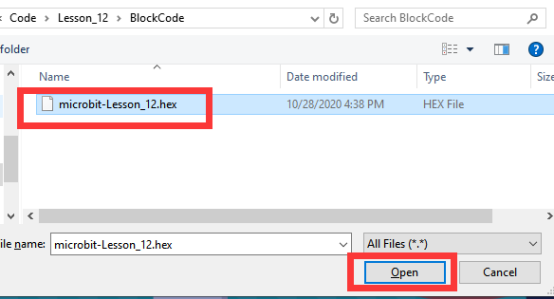
Select the file in ".hex" format and click the Open:
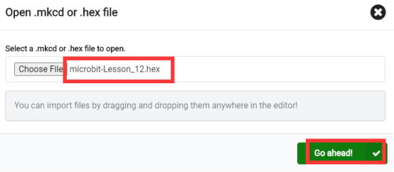
2. Notice whether the file has been loaded into the following window, and then click the "Go ahead!" button, as shown in the following figure:
3. Open the file successfully, as shown in the following figure:
12.6.2 Run the program
1. After the program is written, connect micro:bit and PC with a Micro USB cable.
2. After micro:bit is connected to the computer, you need to first "Pair device". Click the  button on the right of
  in the lower left corner, and then click the
  option, as shown in the following figure:

Then click  in the lower right corner:

Then the following dialog box will pop up, select  , and then click

After the device is successfully paired, the  button changes to

3. Start to download the program to Micro:bit, and click the  button. Generally, the program will be downloaded directly to the Micro:bit. After the download is completed, your Micro:bit will restart and run the program just downloaded.Observe the LED screen of the Micro:bit. If this is the first time you have used a Micro:bit magnetic field sensor, the pattern of the LED matrix will be the“TILT TO FILL SCREEN”.At this time, you need to debug the Micro:bit, and for specific methods, see the "12.4" section of this lesson.
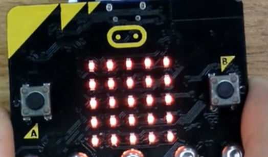
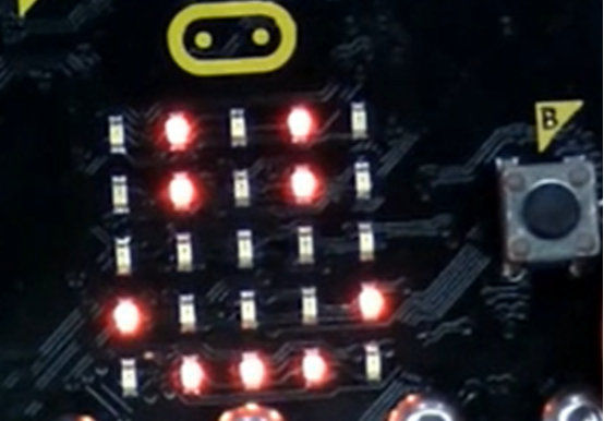
When you calibrate the Micro:bit compass, you need to light up every LED, as shown in the following figure:
After calibration, a smiling face pattern will appear on the LED screen, as shown in the following figure:
4.You need to rotate the Micro:bit horizontally, download a“compass”app on your phone and observe the change of the arrow direction on the LED screen combining with the app.

[Note]:
If Micro:bit doesn't respond after clicking the  , you need to click the
  button on the right of the
  , and then click the
  , and observe the situation of the Micro:bit again, as shown in the following figure:

If you have problems, please send us an email: support@adeept.com
12.6.3 Learn the code program
In the program, we use the following instruction blocks, which are explained as follows:
Block | Function |
| This is an instruction block to calibrate the compass. |
| This is an instruction block to obtain the direction of the compass. |
| This is an arrow pattern instruction block to show the direction on the LED screen. |
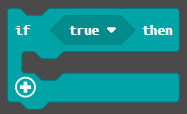
| This is an instruction block for the conditional judgment statement of the“if true/false then”. |
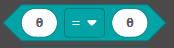
| This is a comparison operator instruction block. |
| This is an instruction block for the “and” comparison operator |

12.7 Python programming
12.7.1 Run the program
1.Connect micro:bit and PC with a Micro USB cable.
2. Open the Mu Editor installed on the computer, and click the button [Load] in the upper left corner to open the source code program of this lesson:

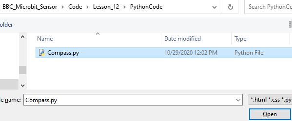
Find the code file for this lesson:
BBC_Microbit_Sensor\Code\Lesson_12\PythonCode
Select the file in ".py" format and click the Open:
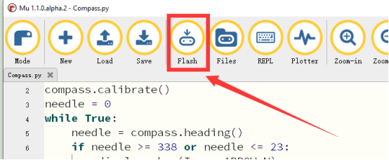
3. Click the [Flash] button to download the program to Micro:bit, as shown in the following figure:
4.After the program is downloaded, you need to rotate the Micro:bit horizontally, download a“compass”app to your phone and observe the change of the arrow direction on the LED screen combining with the app.
【Note】:
After you click the [Flash] button, if there is no change on the LED screen of Micro:bit, you need to restart the Micro:bit, and then click the [Flash] button again.
If you have problems, please send us an email: support@adeept.com
12.7.2 Learn the code program
The source codes are as follows:
1 2 3 4 5 6 7 8 9 10 11 12 13 14 15 16 17 18 19 20 21 | from microbit import * compass.calibrate() needle = 0 while True: needle = compass.heading() if needle >= 338 or needle <= 23: display.show(Image.ARROW_N) elif needle > 23 and needle < 68: display.show(Image.ARROW_NE) elif needle >= 68 and needle <= 113: display.show(Image.ARROW_E) elif needle > 113 and needle < 158: display.show(Image.ARROW_SE) elif needle >= 158 and needle <= 203: display.show(Image.ARROW_S) elif needle > 203 and needle < 248: display.show(Image.ARROW_SW) elif needle >= 248 and needle <= 293: display.show(Image.ARROW_W) elif needle > 293 and needle < 338: display.show(Image.ARROW_NW) |
(1)Starts the calibration process. An instructive message will be scrolled to the user after which they will need to rotate the device in order to draw a circle on the LED display.
2 | compass.calibrate() |
(2)compass.heading():Gives the compass heading, calculated from the above readings, as an integer in the range from 0 to 360, representing the angle in degrees, clockwise, with north as 0.
5 | needle = compass.heading() |
(3) You can determine which direction the compass is pointing in by determining the angle that the needle points to.
If you don't like to use arrows to indicate directions, you can use this statement to output the corresponding direction:
display.show(“N”) # ‘N’ means due north
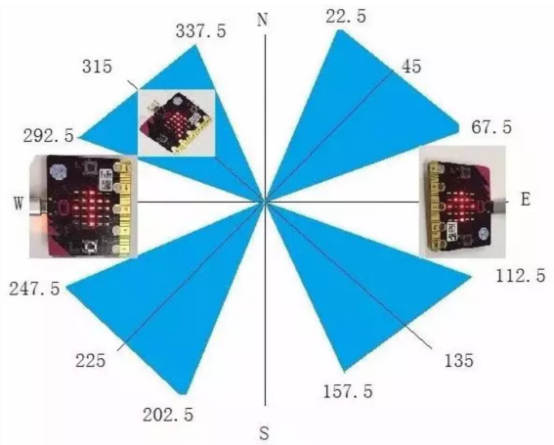
6 7 8 9 10 11 12 13 14 15 16 17 18 19 20 21 | if needle >= 338 or needle <= 23: display.show(Image.ARROW_N) elif needle > 23 and needle < 68: display.show(Image.ARROW_NE) elif needle >= 68 and needle <= 113: display.show(Image.ARROW_E) elif needle > 113 and needle < 158: display.show(Image.ARROW_SE) elif needle >= 158 and needle <= 203: display.show(Image.ARROW_S) elif needle > 203 and needle < 248: display.show(Image.ARROW_SW) elif needle >= 248 and needle <= 293: display.show(Image.ARROW_W) elif needle > 293 and needle < 338: display.show(Image.ARROW_NW) |