In this lesson, we will carry out an interesting experiment by programming on the Micro:bit so as to control LED with Limit Switch.
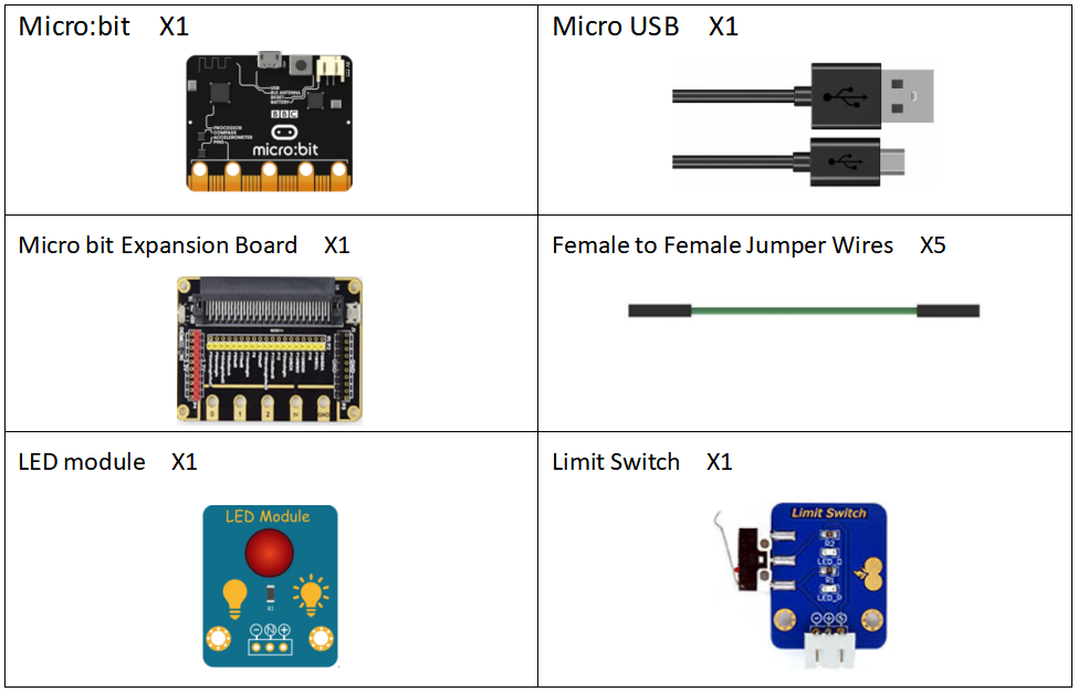
18.1 Components to be prepared
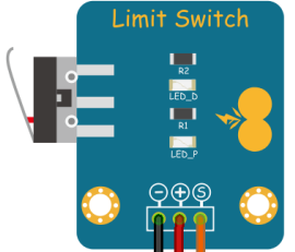
18.2 The Limit Switch module
18.2.1 The Limit Switch module
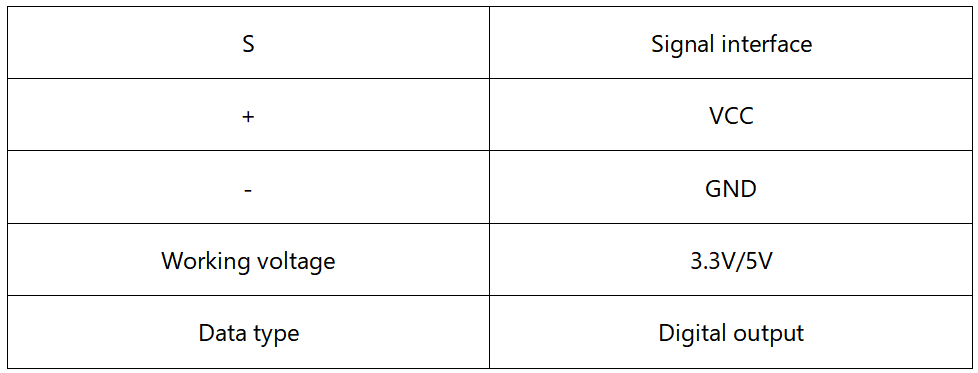
The Limit switch is a digital sensor with a small LED light on the board, which visually displays the status of the collision switch. The board has a high-quality interface that can withstand tens of thousands of plugs and unplugs to ensure the firmness of the contact port. It is connected through a 3P sensor It is very easy to realize the interactive works related to collision by plugging into the dedicated micro:bit expansion board.It has the following parameters:
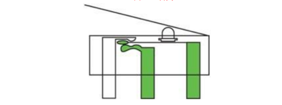
The working principle of The Limit switch is very simple. It relies on the internal mechanical structure to complete the conduction and interruption of the circuit. When the external detection arm of the Limit switch is collided, the detection arm is pressed down by force, driving the reed inside the Limit switch to toggle, and the conduction state of the circuit is changed.
18.3 Low level and high level
In circuit, the form of binary (0 and 1) is presented as low level and high level.
Low level is generally equal to ground voltage (0V). High level is generally equal to the operating voltage of components.
The low level of Micro:bit is 0V and high level is 3.3V, as shown below. When IO port on Micro:bit outputs high level, low-power components can be directly driven,like LED.

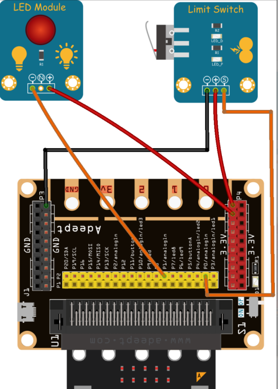
18.4 Circuit
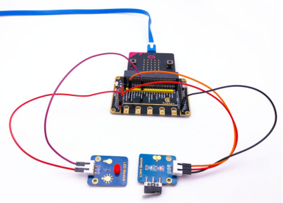
You need to connect the components according to the circuit diagram below.
18.5 MakeCode programming
Next, we will use the online MakeCode Editor to complete the experiment in this lesson.
18.5.1 Start programming
(1) Log in to the website
1. You need to enter the URL in the address bar of Google Browser:
https://makecode.microbit.org/
2. After the website is successfully opened, the interface as shown below will appear:

(2) Import a project
1. In the HOME interface, click the "Import" button to import the external ".hex" file:

In the pop-up dialog box, select the "Import File", as shown in the following figure:

Click the "Choose File"

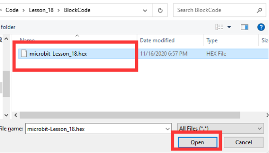
Find the code file for this lesson:
BBC_Microbit_Sensor\Code\Lesson_18\BlockCode
Select the file in ".hex" format and click the Open:
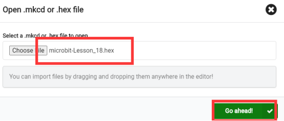
2. Notice whether the file has been loaded into the following window, and then click the "Go ahead!" button, as shown in the following figure:
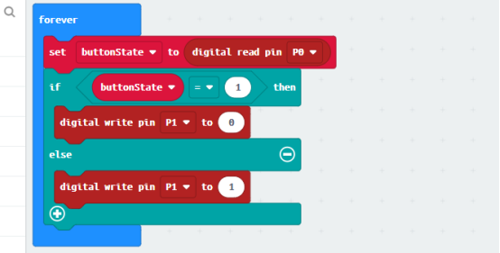
3.You can see the following interface when successfully opening the file:
18.5.2 Run the program
1. After the program is written, connect micro:bit and PC with a Micro USB cable.
2. After micro:bit is connected to the computer, you need to first "Pair device". Click the  button on the right of
  in the lower left corner, and then click the
  option, as shown in the following figure:

Then click  in the lower right corner

Then the following dialog box will pop up, select  , and then click

After the device is successfully paired, the  button changes to

3. Start to download the program to Micro:bit, and click the  button. Generally, the program will be downloaded directly to the Micro:bit. After the download is completed, your Micro:bit will restart and run the program just downloaded. Press Limit Switch and see whether LED is on or not. That LED is on suggests a success, as shown below:

[Note]
If Micro:bit doesn't respond after clicking the  , you need to click the
  button on the right of the
  , and then click the
  , and observe the situation of the LED again, as shown in the following figure:

If you have problems, please send us an email: support@adeept.com
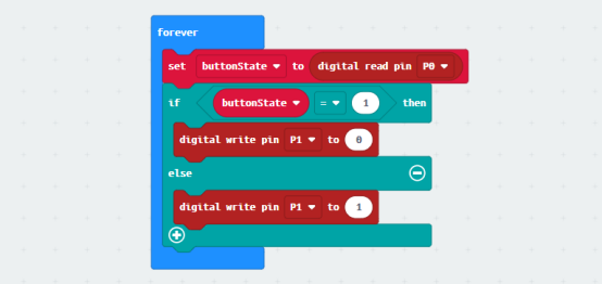
18.5.3 Learn the code program
The following instruction blocks will be applied in the program. Please see the description of the function as follows:
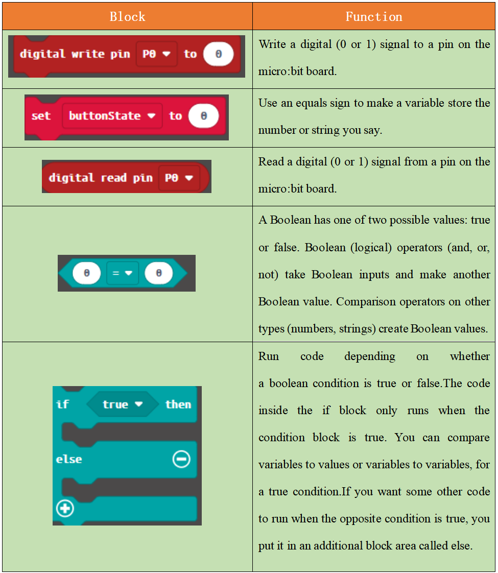
Get the status of Limit Switch with buttonState; if buttonState = 1, it suggests that the Limit Switch is being pressed. And the LED will be switched on, when a low level (represented by 0) signal is sent to LED through 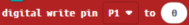 ; while a high level (represented by 1) signal is sent, LED will be switched off.
18.6 Python programming
18.6.1 Run the program
1.Connect micro:bit and PC with a Micro USB cable.
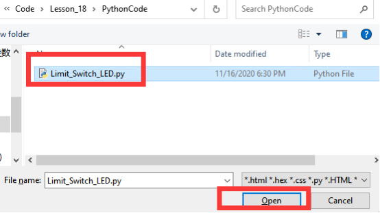
2. Open the Mu Editor installed on the computer, and click the button [Load] in the upper left corner to open the source code program of this lesson:

Find the code file for this lesson:
BBC_Microbit_Sensor\Code\Lesson_18\PythonCode
Select the file in ".py" format and click the Open:
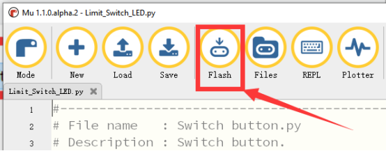
3. Click the [Flash] button to download the program to Micro:bit, as shown in the following figure:
4.When successfully downloading the program, press Limit Switch. When LED is on, it suggests that the experiment is a success.
If you have problems, please send us an email: support@adeept.com
18.6.2 Learn the code program
Get the status of Limit Switch with buttonState = pin0.read_digital(). If buttonState == 1, it suggests that the Limit Switch is being pressed. And the LED will be switched on, when a low level (represented by 0) signal is sent to LED through pin1.write_digital(0); while a high level (represented by 1) signal is sent, LED will be switched off.
11 12 13 14 15 16 17 | while True: buttonState = pin0.read_digital() if buttonState == 1: pin1.write_digital(0) else: pin1.write_digital(1) sleep(20) |