In this lesson, we will carry out an interesting experiment by programming on the Micro:bit so as to control LED patterns with buttons.
17.1 Components to be prepared
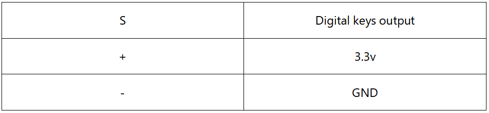
17.2 Button
17.2.1 What is a Button?
Button is one of the most common input devices. There are two non-touching touch pieces inside a common Button. When the Button is pressed by external force, the two touch pieces are connected together and the circuit is connected. After the external force is released, it returns to the disconnected state, that is, the circuit is disconnected. Many functions can be achieved when used in conjunction with other components. Its operation is intuitive and effective, and many operations need to be controlled by Button. Almost all electronic devices have the design of Button reserved. Let's learn how to realize simple Button operation on raspberry pie.

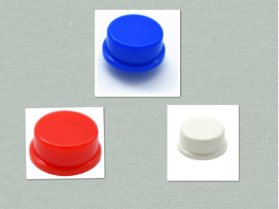
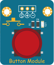
The Button used in this lesson is as following figure:
17.2.2 Experimental principles
We control the state of the LED by judging the state of the GPIO port connected to the Button. Since the Arduino IO port can be used as output mode to light up the light, it can also be used as input mode to detect the high and low level of the IO port. Here, when we detect the Button pressed, we give the Arduino IO port a low level, indicating that the Button has been pressed, then we will light the LED. When we detect the release of the Button, we give the Arduino IO port a high level, which means that the Button has been released, and then we will turn off the LED.
17.2.3 Dealing with Button jitter
The button jitter must happen in the process of using. The jitter waveform is as the flowing:
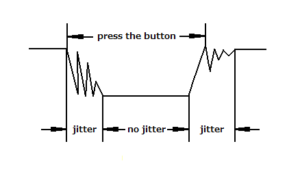
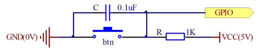
Each time you press the button, the Arduino will think you have pressed the button many times due to the jitter of the button. We have to deal with the jitter of buttons before we use the button. We can remove the jitter of buttons through the software programming, besides, we can use a capacitance to remove the jitter of buttons. Here we introduce the software method. First, we detect whether the level of button interface is low level or high level. When the level we detected is low level, 5~10 MS delay is needed, and then detect whether the level of button interface is low or high. If the signal is low, we can confirm that the button is pressed once. You can also use a 0.1uF capacitance to clean up the jitter of buttons. The schematic diagram is shown in below.
The button we used is a normally open type button. The two contacts of a button is in the off state under the normal conditions, only when the button is pressed they are closed.
17.3 Low level and high level
In circuit, the form of binary (0 and 1) is presented as low level and high level.
Low level is generally equal to ground voltage (0V). High level is generally equal to the operating voltage of components.
The low level of Micro:bit is 0V and high level is 3.3V, as shown below. When IO port on Micro:bit outputs high level, low-power components can be directly driven,like LED.

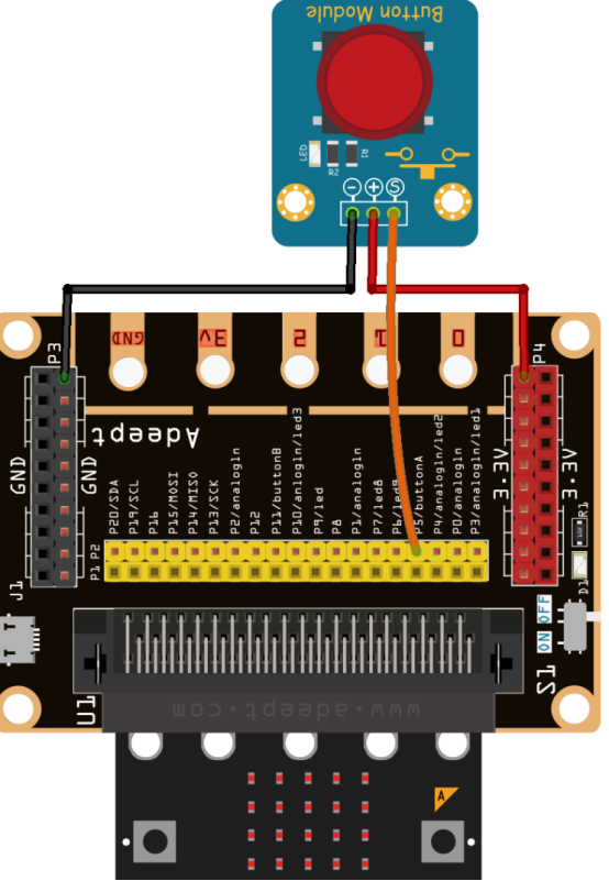
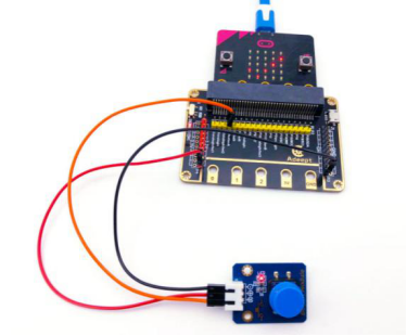
17.4 Circuit
You need to connect the components according to the circuit diagram below.
17.5 MakeCode programming
Next, we will use the online MakeCode Editor to complete the experiment in this lesson.
17.5.1 Start programming
(1) Log in to the website
1. You need to enter the URL in the address bar of Google Browser:
https://makecode.microbit.org/
2. After the website is successfully opened, the interface as shown below will appear:

(2) Import a project
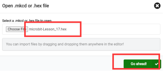
1. In the HOME interface, click the "Import" button to import the external ".hex" file:

In the pop-up dialog box, select the "Import File", as shown in the following figure:

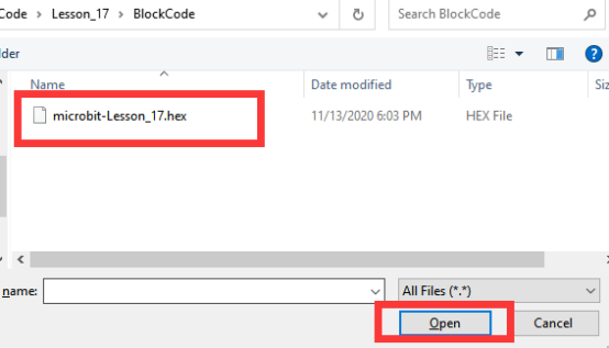
Click the "Choose File"

Find the code file for this lesson:
BBC_Microbit_Sensor\Code\Lesson_17\BlockCode
Select the file in ".hex" format and click the Open:
2. Notice whether the file has been loaded into the following window, and then click the "Go ahead!" button, as shown in the following figure:
3.You can see the following interface when successfully opening the file:
17.5.2 Run the program
1. After the program is written, connect micro:bit and PC with a Micro USB cable.
2. After micro:bit is connected to the computer, you need to first "Pair device". Click the  button on the right of
  in the lower left corner, and then click the
  option, as shown in the following figure:

Then click  in the lower right corner

Then the following dialog box will pop up, select  , and then click

After the device is successfully paired, the  button changes to

3. Start to download the program to Micro:bit, and click the  button. Generally, the program will be downloaded directly to the Micro:bit. After the download is completed, your Micro:bit will restart and run the program just downloaded. Press the button, and you will see that LED patterns disappear. Release the button, and you will see that LED patterns appear, as shown below:
[Note]
1.If Micro:bit doesn't respond after clicking the  , you need to click the
  button on the right of the
  , and then click the
  , and observe the situation of the Micro:bit again, as shown in the following figure:

2. If no experimental phenomenon is observed, please re-plug the USB cable connected to the Micro:bit, and then download the program again.
If you have problems, please send us an email: support@adeept.com
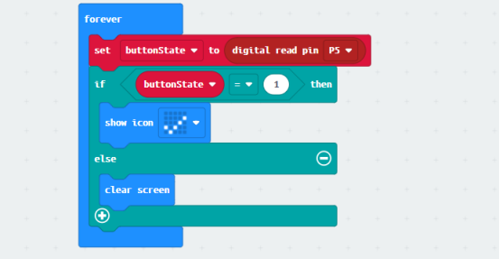
17.5.3 Learn the code program
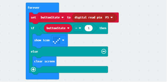
The following instruction blocks will be applied in the program. Please see the description of the function as follows:
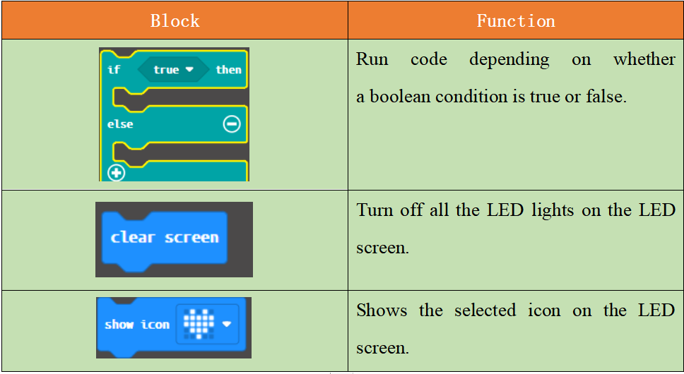
When release the button, a pattern will appear for a long time: "√"; when press the button, the LED screen will be cleared completely.
17.6 Python programming
17.6.1 Run the program
1.Connect micro:bit and PC with a Micro USB cable.
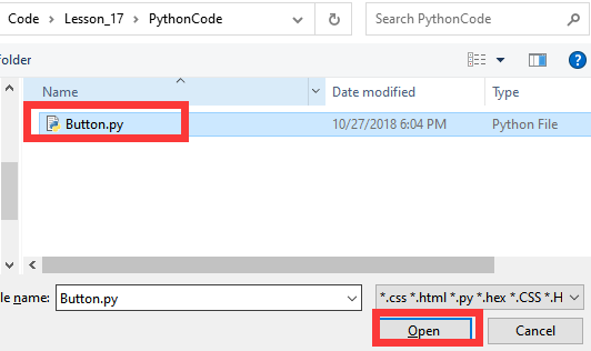
2. Open the Mu Editor installed on the computer, and click the button [Load] in the upper left corner to open the source code program of this lesson:

Find the code file for this lesson:
BBC_Microbit_Sensor\Code\Lesson_17\PythonCode
Select the file in ".py" format and click the Open:
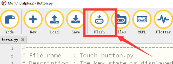
3. Click the [Flash] button to download the program to Micro:bit, as shown in the following figure:
4. When successfully downloading the program, press the button, and a pattern will disappear. When release the button, the pattern will appear.

If you have problems, please send us an email: support@adeept.com
17.6.2 Learn the code program
The source codes are as follows:
9 10 11 12 13 14 15 16 17 | from microbit import *
while True: buttonState = pin5.read_digital() if buttonState==1: display.show(Image.YES) else: display.clear() sleep(20) |
(1)When release the button, a pattern will appear for a long time: "√"; when press the button, the LED screen will be cleared completely.
11 12 13 14 15 16 17 | while True: buttonState = pin5.read_digital() if buttonState==1: display.show(Image.YES) else: display.clear() sleep(20) |