In this lesson, we will carry out an interesting experiment to change the color of the RGB LED by programming on the Micro:bit.
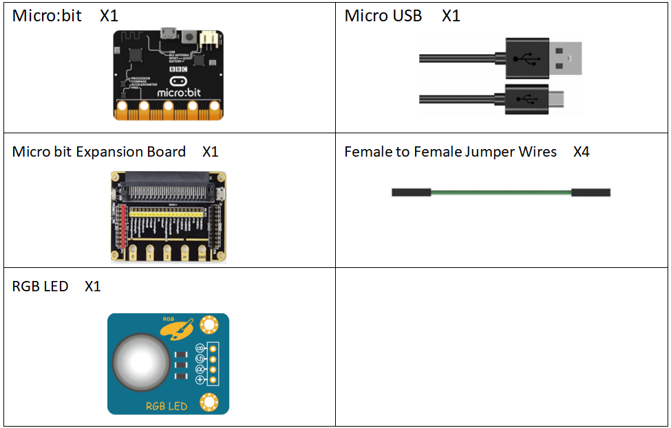
21.1 Components to be prepared
21.2 The introduction of RGB LED
21.2.1 RGB LED
The RGB LED consists of three LEDs. Each LED has a red, a green and a blue light. The three-color LEDs can produce any color; it contains the red, green and blue emitters, typically with a four-wire connection and a common wire (anode or cathode). These LEDs can have a common anode or a common cathode wire.
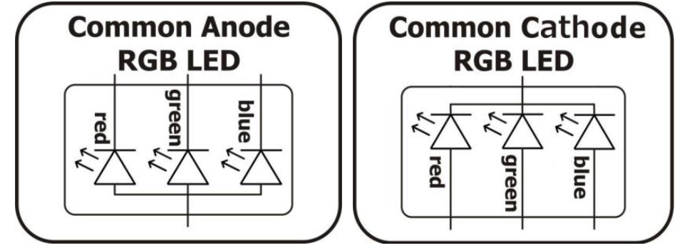
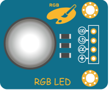
We used the common anode RGB LED in this experiment. Made it into a module, from left to right we can see the common anode, R, G, B, where R, G, B are connected respectively with three SMD resistors. The longest pin is the common anode of the three LEDs.
21.3 Low level and high level
In circuit, the form of binary (0 and 1) is presented as low level and high level.
Low level is generally equal to ground voltage (0V). High level is generally equal to the operating voltage of components.
The low level of Micro:bit is 0V and high level is 3.3V, as shown below. When IO port on Micro:bit outputs high level, low-power components can be directly driven,like LED.

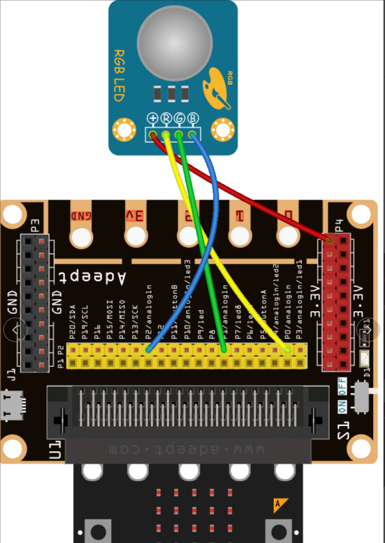
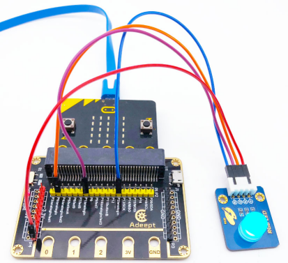
21.4 Circuit
You need to connect the components according to the circuit diagram below.
21.5 MakeCode programming
Next, we will use the online MakeCode Editor to complete the experiment in this lesson.
21.5.1 Start programming
(1) Log in to the website
1. You need to enter the URL in the address bar of Google Browser:
https://makecode.microbit.org/
2. After the website is successfully opened, the interface as shown below will appear:

(2) Import a project
1. In the HOME interface, click the "Import" button to import the external ".hex" file:

In the pop-up dialog box, select the "Import File", as shown in the following figure:

Click the "Choose File"

Find the code file for this lesson:
BBC_Microbit_Sensor\Code\Lesson_21\BlockCode
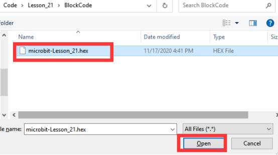
Select the file in ".hex" format and click the Open:
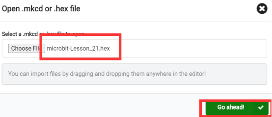
2. Notice whether the file has been loaded into the following window, and then click the "Go ahead!" button, as shown in the following figure:
3.You can see the following interface when successfully opening the file:
21.5.2 Run the program
1. After the program is written, connect micro:bit and PC with a Micro USB cable.
2. After micro:bit is connected to the computer, you need to first "Pair device". Click the  button on the right of
  in the lower left corner, and then click the
  option, as shown in the following figure:

Then click  in the lower right corner

Then the following dialog box will pop up, select  , and then click

After the device is successfully paired, the  button changes to

3. Start to download the program to Micro:bit, and click the  button. Generally, the program will be downloaded directly to the Micro:bit. After the download is completed, your Micro:bit will restart and run the program just downloaded. If the color of the RGB LED changes, it indicates a success of the experiment:
[Note]
If the RGB LED has no change in color after the  , you need to click the
  button on the right of the
  , and then click the
  , and observe the situation of the RGB LED again, as shown in the following figure:

If you have problems, please send us an email: support@adeept.com
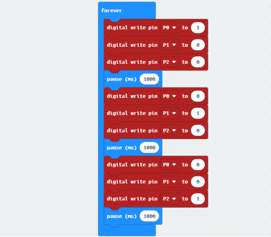
21.5.3 Learn the code program
The following instruction blocks will be applied in the program. Please see the description of the function as follows:
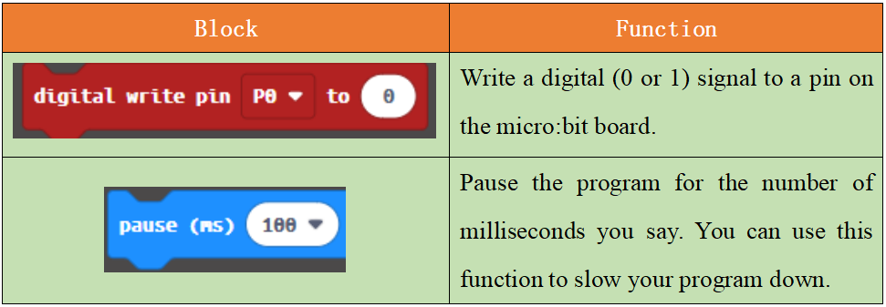
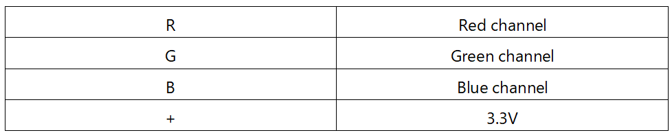
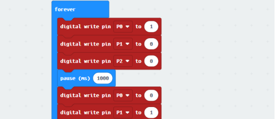
You can send signal 1 or 0 to the RGB LED connected to the P0, P1 and P2 through the instruction blocks such as 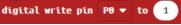 . P0, P1 and P2 correspond to ‘R’, ‘G’, ‘B’ respectively. So you can click different instruction portfolios to make the RGB LED light different colors.
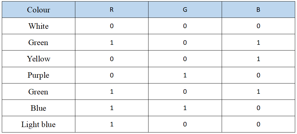
A table of common RGB color values is shown below:
21.6 Python programming
21.6.1 Run the program
1.Connect micro:bit and PC with a Micro USB cable.
2. Open the Mu Editor installed on the computer, and click the button [Load] in the upper left corner to open the source code program of this lesson:

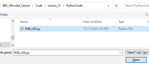
Find the code file for this lesson:
BBC_Microbit_Sensor\Code\Lesson_21\PythonCode
Select the file in ".py" format and click the Open:
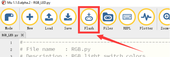
3. Click the [Flash] button to download the program to Micro:bit, as shown in the following figure:
4.After the program is downloaded, if the RGB LED has a change in color, it indicates the success of the experiment.

If you have problems, please send us an email: support@adeept.com
21.6.2 Learn the code program
The method of set_rgb() can be used to change the color of the RGB LED, but the parameters only can be 1023 or 0.
12 13 14 15 16 17 18 19 20 21 22 | def set_rgb(red, green, blue): pin0.write_analog(red) pin1.write_analog(green) pin2.write_analog(blue) while True: set_rgb(1023, 0, 0) sleep(1000) set_rgb(0, 1023, 0) sleep(1000) set_rgb(0, 0, 1023) sleep(2000) |