In this lesson, we will carry out an interesting experiment to customize and display a pattern on the Micro:bit.
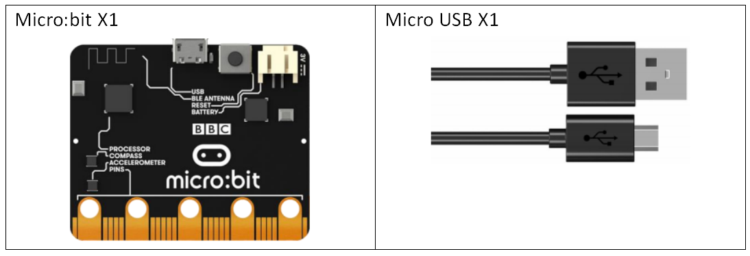
8.1 Components to be prepared
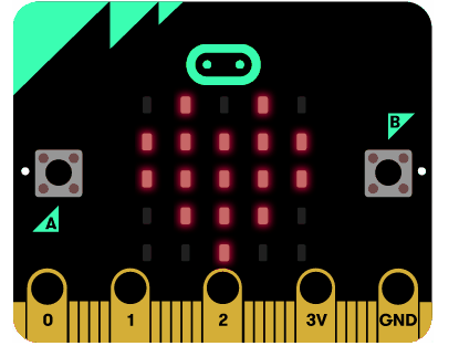
8.2 LED display
The front LED display of Micro:bit consists of 25 5x5 lattice LEDs.
25 LEDs arranged in a 5x5 grid make up the display for showing pictures, words and numbers.
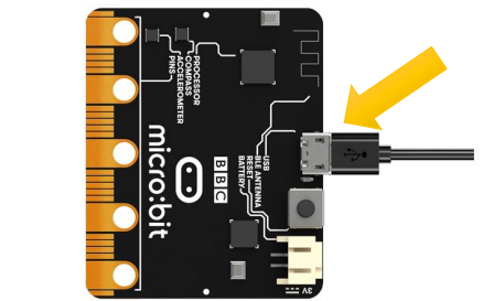
8.3 Circuit
Connect micro:bit and PC with a Micro USB cable.
8.4 MakeCode programming
We will use an online MakeCode Editor to complete the experiment in this lesson, as shown below.
8.4.1 Start programming
(1) Log in to the website
1. You need to enter the URL in the address bar of Google Browser:
https://makecode.microbit.org/
2. After the website is successfully opened, the interface as shown below will appear:

(2) Import a project
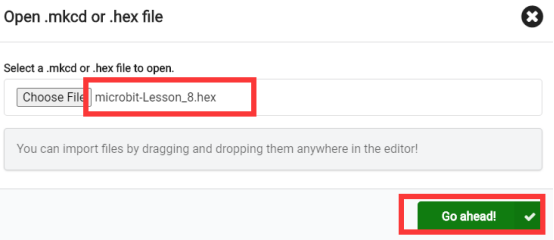
1. In the HOME interface, click the "Import" button to import the external ".hex" file:

In the pop-up dialog box, select the "Import File", as shown in the following figure:

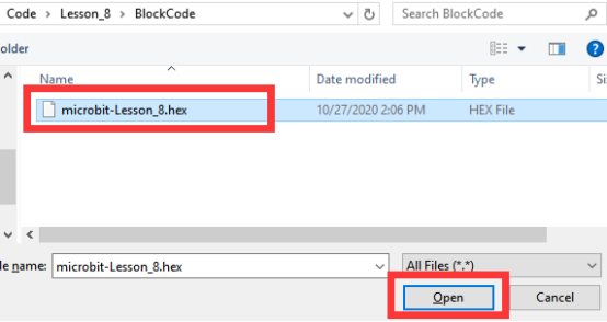
Click the "Choose File"

Find the code file for this lesson:
BBC_Microbit_Sensor\Code\Lesson_8\BlockCode
Select the file in ".hex" format and click the Open:
2. Notice whether the file has been loaded into the following window, and then click the "Go ahead!" button, as shown in the following figure:
3. Open the file successfully, as shown in the following figure:
8.4.2 Run the program
1. After the program is written, connect micro:bit and PC with a Micro USB cable.
2. After micro:bit is connected to the computer, you need to first "Pair device". Click the  button on the right of
  in the lower left corner, and then click the
  option, as shown in the following figure:

Then click  in the lower right corner

Then the following dialog box will pop up, select  , and then click

After the device is successfully paired, the  button changes to

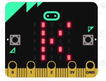
3. Start to download the program to Micro:bit, and click the  button. Generally, the program will be downloaded directly to the Micro:bit. After the download is completed, your Micro:bit will restart and run the program just downloaded.then the pattern on the LED screen of the Micro:bit is as follows:
[Note]:
If Micro:bit doesn't respond after clicking the  , you need to click the
  button on the right of the
  , and then click the
  , and observe the situation of the Micro:bit again, as shown in the following figure:

If you have problems, please send us an email: support@adeept.com
8.4.3 Learn the code program
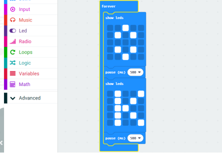
In the program, we use the following instruction blocks, which are explained as follows:
Block | Function |
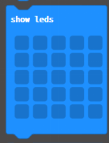
| This is an instruction block that can customize and display patterns. It correspond to the 5x5 matrix LED on the LED screen. You can depict the pattern you like by clicking the corresponding “LED” with the mouse. |
8.5 Python programming
8.5.1 Run the program
1.Connect micro:bit and PC with a Micro USB cable.
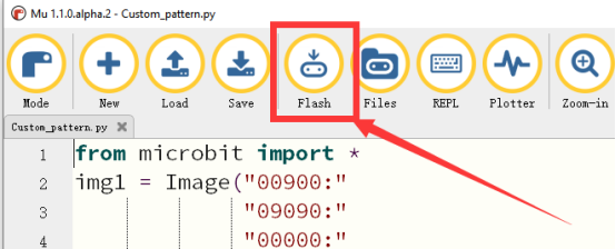
2. Open the Mu Editor installed on the computer, and click the button [Load] in the upper left corner to open the source code program of this lesson:

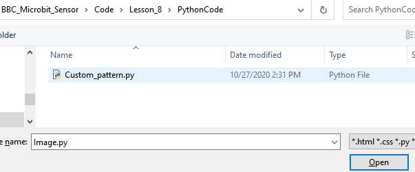
Find the code file for this lesson:
BBC_Microbit_Sensor\Code\Lesson_8\PythonCode
Select the file in ".py" format and click the Open:
3. Click the [Flash] button to download the program to Micro:bit, as shown in the following figure:
4.After the program is downloaded, the pattern will be displayed on the LED screen of the Micro:bit.

【Note】:
After you click the [Flash] button, if there is no change on the LED screen of Micro:bit, you need to restart the Micro:bit, and then click the [Flash] button again.
If you have problems, please send us an email: support@adeept.com
8.5.2 Learn the code program
The source codes are as follows:
1 2 3 4 5 6 7 8 9 10 11 12 13 14 15 16 | from microbit import * img1 = Image("00900:" "09090:" "00000:" "09090:" "00900") img2 = Image("09009:" "09090:" "09900:" "09090:" "09009") while True: display.show(img1) sleep(1000) display.show(img2) sleep(1000) |
(1)Create an image in the code and define it as img, then display the defined image in a while loop. As shown in the code below, the parameters in Image consist of 5 strings. Each line of characters corresponds to a row of LEDs. Each digit represents the brightness of an LED. The value ranges from 0 to 9, the larger the number, the brighter the LED.
2 3 4 5 6 | img1 = Image("00900:" "09090:" "00000:" "09090:" "00900") |
In the code program, we use the “Image” library. More graphic schemes and methods of use about the “Image” library are available in the link below:
https://microbit-micropython.readthedocs.io/en/latest/image.html