In this lesson, we will carry out an interesting experiment by programming on the Micro:bit so as to display the information on LCD1602 screen.
26.1 Components to be prepared
26.2 LCD1602 and IIC Interface Module
26.2.1 LCD1602
1602 crystal is also called 1602 character crystal. 1602 LCD means that the display content is 16X2, that is, it can display two lines, each line of 16 characters LCD module, it is a kind of dot matrix type specially used to display letters, numbers, symbols, etc. It consists of several 5X7 or 5X11 dot matrix characters, each of which can display one character. The character bits are separated by one dot pitch and there's a gap between each line. Therefore, characters are spaced within and between lines.
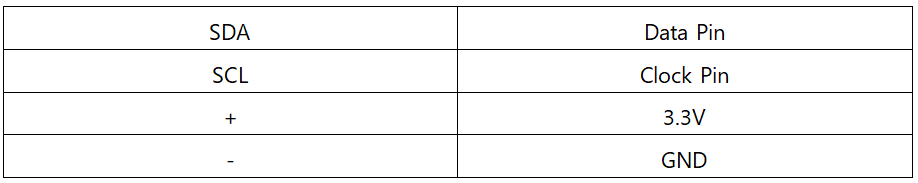
Pins of an LCD screen are as follows:
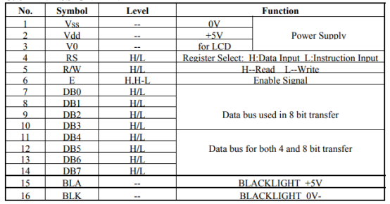
We can clearly see on the table above that 1, 2 are the power wires. The voltage of the pin 3 can be used to adjust the contrast of the screen. Pin 4 RS is data and command selection; pin 5 RW is read and write control. Pin 6 EN is a data transfer enable pin, like a clock signal, when a pulse is generated, the data on the data pin is transferred to the LCD. DB0-DB8 is the data port of the liquid crystal. Users can choose the 8-bit transmission mode or switch to the 4-bit transmission mode.
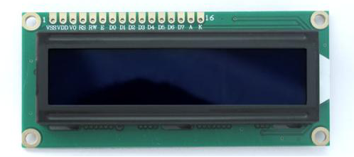
LCD 1602:
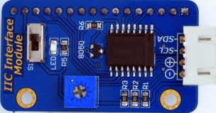
26.2.2 IIC Interface Module
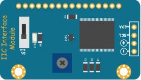
The IO ports of the micro: bit is limited. We need a lot of ports if we want to directly drive the LCD1602. But there may be not enough ports to connect other sensors. In order to solve this problem, a PCF8574-based I2C interface module is used here. It is to expand the IO ports of the micro: bit so that only two pins (SDA and SCL) are needed to control the LCD1602 and to save many ports to connect more sensors.
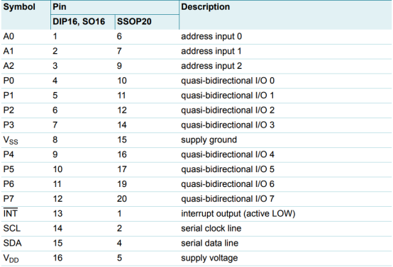
PCF8574 pin information:
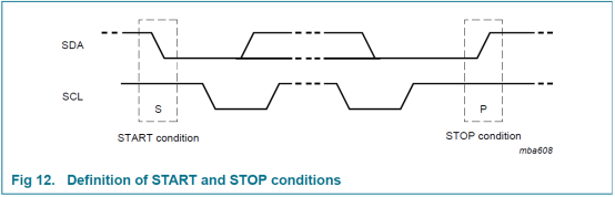
IIC communication protocol:
Two bus lines, one data line SDA and one clock line SCL.
The IIC bus has three types of signals in the process of transmitting data: start signal, end signal, and response signal.
Start signal: When SCL is high, SDA transfers from high level to low level and starts transmitting data.
End signal: When SCL is high, SDA transfers from low level to high level and ends transmitting data.
Response signal: After receiving the 8-bit data, the receiving IC sends a specific low-level pulse to the sending IC, indicating that the data has been received.
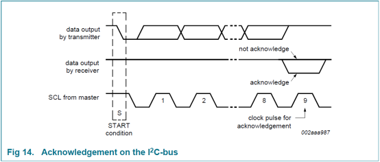
After the CPU sends a signal to the controlled unit, it waits for the controlled unit to send a response signal. After receiving the response signal, the CPU makes a judgment as to whether to continue transmitting the signal according to the actual situation. If the response signal is not received, it is judged to be an error occurs in the controlled unit.
IIC interface module:
26.2.3 Working principle of the LCD1602
The LCD1602 character liquid crystal display module is a dot-matrix LCD specifically for displaying letters, numbers, and symbols. Commonly used modules are 16×1, 16×2, 20×2, and 40×2. The internal controller of the general LCD1602 character liquid crystal display is mostly HD44780, which can display English letters, Arabic numerals, Japanese Katakana and general symbols.
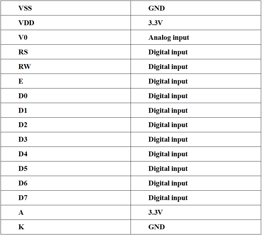
LCD1602 is a kind of character LCD display. The LCD has a parallel interface, meaning that the microcontroller has to manipulate several interface pins at once to control the display. The interface consists of the following pins:
● A register select (RS) pin that controls where in the LCD's memory you're writing data to. You can select either the data register, which holds what goes on the screen, or an instruction register, which is where the LCD's controller looks for instructions on what to do next.
● A Read/Write (R/W) pin that selects reading mode or writing mode
● An Enable pin that enables writing to the registers
● 8 data pins (D0-D7). The state of these pins (high or low) is the bits that you're writing to a register when you write, or the values when you read.
● There are also a display contrast pin (Vo), power supply pins (+5V and Gnd) and LED Backlight (Bklt+ and BKlt-) pins that you can use to power the LCD, control the display contrast, and turn on or off the LED backlight respectively.
The process of controlling the display involves putting the data that form the image of what you want to display into the data registers, then putting instructions in the instruction register. The LiquidCrystal Library simplifies this for you so you don't need to know the low-level instructions.
The Hitachi-compatible LED can be controlled in two modes: 4-bit or 8-bit. The 4-bit mode requires seven I/O pins from the Arduino, while the 8-bit mode requires 11 pins. For displaying text on the screen, you can do most everything in 4-bit mode, so example shows how to control a 2x16 LCD in 4-bit mode.
26.3 Low level and high level
In circuit, the form of binary (0 and 1) is presented as low level and high level.
Low level is generally equal to ground voltage (0V). High level is generally equal to the operating voltage of components.
The low level of Micro:bit is 0V and high level is 3.3V, as shown below. When IO port on Micro:bit outputs high level, low-power components can be directly driven,like LED.

26.4 Circuit
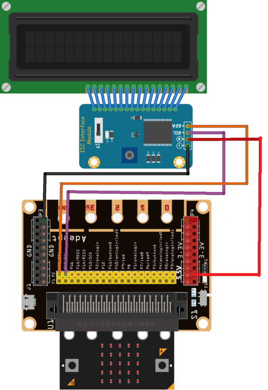
You should connect the components according to the following circuit diagram, and view the pictures with the function “Zoom in”: The "+" of IIC Interface Module shall be connected to the pin “5.5V” on Micro bit Expansion Board with connecting to the external power supply:
26.5 MakeCode programming
Next, we will use the online MakeCode Editor to complete the experiment in this lesson.
26.5.1 Start programming
(1) Log in to the website
1. You need to enter the URL in the address bar of Google Browser:
https://makecode.microbit.org/
2. After the website is successfully opened, the interface as shown below will appear:

(2) Import a project
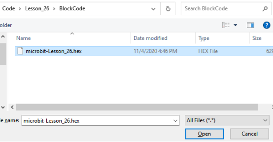
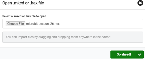
1. In the HOME interface, click the "Import" button to import the external ".hex" file:

In the pop-up dialog box, select the "Import File", as shown in the following figure:

Click the "Choose File"

Find the code file for this lesson:
BBC_Microbit_Sensor\Code\Lesson_26\BlockCode
Select the file in ".hex" format and click the Open:
2. Notice whether the file has been loaded into the following window, and then click the "Go ahead!" button, as shown in the following figure:
3.You can see the following interface when successfully opening the file:
26.5.2 Run the program
1. After the program is written, connect micro:bit and PC with a Micro USB cable.
2. After micro:bit is connected to the computer, you need to first "Pair device". Click the  button on the right of
  in the lower left corner, and then click the
  option, as shown in the following figure:

Then click  in the lower right corner

Then the following dialog box will pop up, select  , and then click

After the device is successfully paired, the  button changes to

3. Start to download the program to Micro:bit, and click the  button. Generally, the program will be downloaded directly to the Micro:bit. After the download is completed, your Micro:bit will restart and run the program just downloaded. You can read the words on LCD1602 screen, as shown below:

[Note]
1.If no experimental phenomenon has been detected after clicking the button  , you need to click the
  button on the right of the
  , and then click the
  , and observe the LCD1602 again, as shown in the following figure:

2. If no experimental phenomenon is observed, you should check whether the USB cable of Micro:bit is successfully connected. If not, please download the program again.
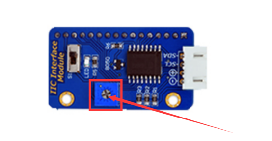
3.After the program is executed, if you cannot see anything on the display or the display is not clear,try rotating the white knob on back of IIC Interface Module slowly, which adjusts the contrast, until the screen can display the Text clearly.
If you have problems, please send us an email: support@adeept.com
26.5.3 Learn the code program
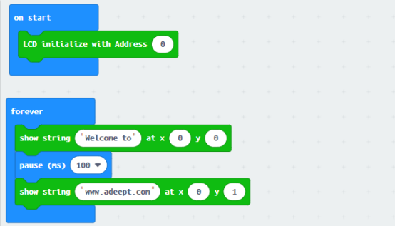
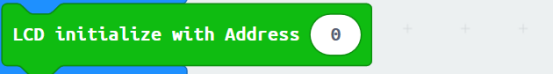
(1)LCD initialization,If you enter 0, it will automatically search for the correct I2C address and connect.
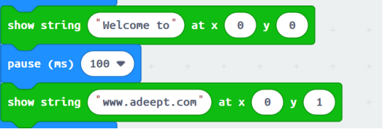
(2)The string is displayed on the LCD1602 screen:
【Note】
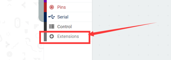
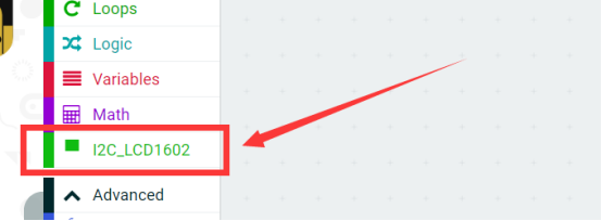
If you want to import the LCD1602 expansion block in a new project, follow the steps below to add it.
(1)Click the button【Extensions】:
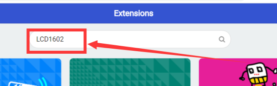
(2)Enter “LCD1602” and click search.
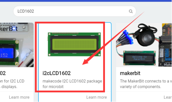
(3)Select“i2cLCD1602”.
(4)Added successfully:
26.6 Python programming
26.6.1 Run the program
1.Connect micro:bit and PC with a Micro USB cable.
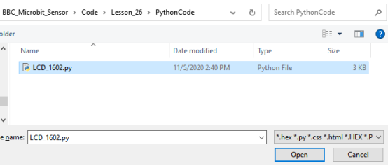
2. Open the Mu Editor installed on the computer, and click the button [Load] in the upper left corner to open the source code program of this lesson:

Find the code file for this lesson:
BBC_Microbit_Sensor\Code\Lesson_26\PythonCode
Select the file in ".py" format and click the Open:
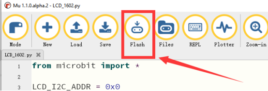
3. Click the [Flash] button to download the program to Micro:bit, as shown in the following figure:
4.After successfully downloading the program, you can read the words on LCD1602 screen, as shown below:

【Note】
(1) If the words on LCD1602 screen cannot be read clearly, connect the external power supply to power the Micro bit Expansion Board with a Micro USB cable.
(2)After the program is executed, if you cannot see anything on the display or the display is not clear,try rotating the white knob on back of IIC Interface Module slowly, which adjusts the contrast, until the screen can display the Text clearly.

If you have problems, please send us an email: support@adeept.com
26.6.2 Learn the code program
The description of the course code in this section is as follows.
(1) As the I2C addresses of the manufacturers’LCD1602 are different (The two common addresses are as follows : 0x27 and 0x3F), all slave addresses can be searched with the scan command, which helps to exclude the I2C addresses(29 and 14)of acceleration sensor and magnetic sensor and finally obtain the address of the newly added I2C device.
3 11 12 13 | LCD_I2C_ADDR = 0x0 for i in i2c.scan(): if i not in [14, 29]: LCD_I2C_ADDR = i |
(2) Display the information on LCD1602 screen with LCD1620().
87 88 89 | sh = LCD1620() sh.puts(" Welcome to") sh.puts(" www.adeept.com", 0, 1) |
【API】
(1)puts(s, x, y)
show a string in given position.
x: 0-15
y: 0-1
(2)char(ch, x, y)
show a character in given position.
x: 0-15
y: 0-1
(3)backlight(on)
on=0: turn of backlight
on=1: turn on backlight
(4)clear()
clear display.
(5)off()
turn off LCD.
(6)on()
turn on LCD.