In this lesson, we will carry out an interesting experiment to control an Active buzzer by programming on a Micro:bit.
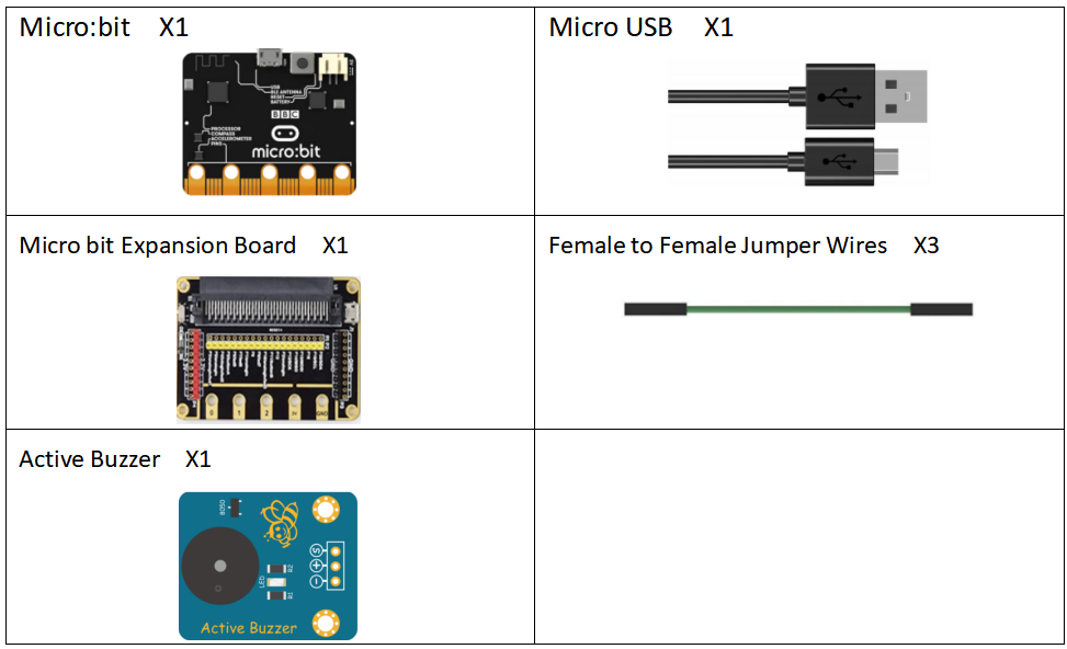
19.1 Components to be prepared
19.2 The introduction of the Buzzer
19.2.1 The Buzzer
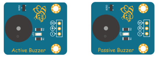
The Buzzer is an electronic sounder with an integrated structure. It is powered by DC voltage and is widely used as a sounding device in electronic products such as computers, printers, copiers, alarms, electronic toys, automotive electronic equipment, telephones, timers, and other electronic products. . There are two types of buzzer: active buzzer and passive buzzer. As shown in the figure below, the left is the active buzzer , and the right is the passive buzzer :
19.2.2 Working principle of the Buzzer
The sounding principle of buzzer is composed of vibration device and resonance device, and buzzer is divided into passive buzzer and active buzzer. The working sounding principle of passive buzzer is: square wave signal input resonant device is converted into sound signal output; the working sounding principle of active buzzer is: DC power input is generated by the amplification sampling circuit of the oscillation system under the action of the resonance device Sound signal. Our course in this section uses an active buzzer. As long as the power is on, the active buzzer will sound. We can program the Micro:bit output high and low alternately, so that the active buzzer will sound.
19.3 Low level and high level
In circuit, the form of binary (0 and 1) is presented as low level and high level.
Low level is generally equal to ground voltage (0V). High level is generally equal to the operating voltage of components.
The low level of Micro:bit is 0V and high level is 3.3V, as shown below. When IO port on Micro:bit outputs high level, low-power components can be directly driven,like LED.

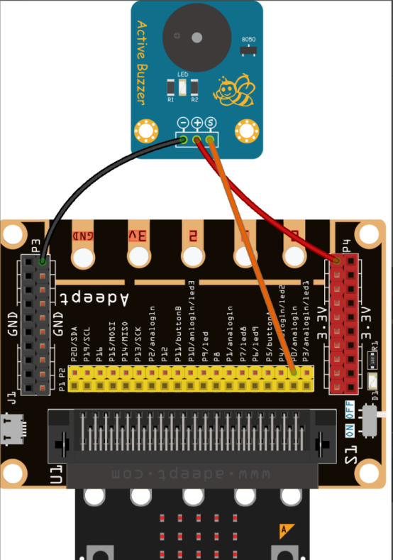
19.4 Circuit
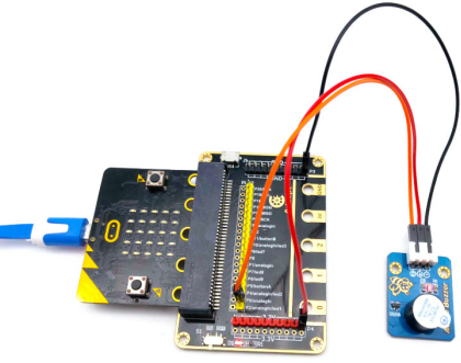
You need to connect the components according to the circuit diagram below.
19.5 MakeCode programming
Next, we will use the online MakeCode Editor to complete the experiment in this lesson.
19.5.1 Start programming
(1) Log in to the website
1. You need to enter the URL in the address bar of Google Browser:
https://makecode.microbit.org/
2. After the website is successfully opened, the interface as shown below will appear:

(2) Import a project
1. In the HOME interface, click the "Import" button to import the external ".hex" file:

In the pop-up dialog box, select the "Import File", as shown in the following figure:

Click the "Choose File"

Find the code file for this lesson:
BBC_Microbit_Sensor\Code\Lesson_19\BlockCode
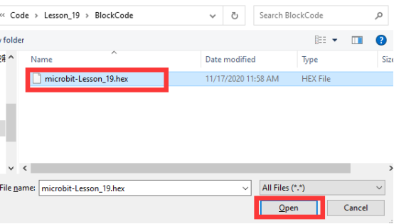
Select the file in ".hex" format and click the Open:
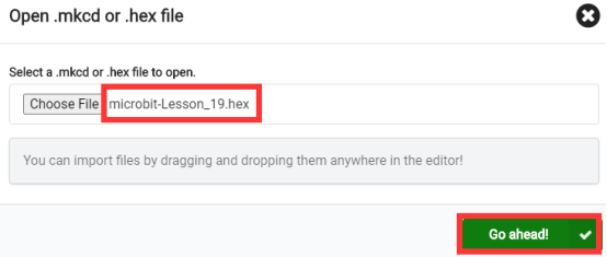
2. Notice whether the file has been loaded into the following window, and then click the "Go ahead!" button, as shown in the following figure:
3.You can see the following interface when successfully opening the file:
19.5.2 Run the program
1. After the program is written, connect micro:bit and PC with a Micro USB cable.
2. After micro:bit is connected to the computer, you need to first "Pair device". Click the  button on the right of
  in the lower left corner, and then click the
  option, as shown in the following figure:

Then click  in the lower right corner

Then the following dialog box will pop up, select  , and then click

After the device is successfully paired, the  button changes to

3. Start to download the program to Micro:bit, and click the  button. Generally, the program will be downloaded directly to the Micro:bit. After the download is completed, your Micro:bit will restart and run the program just downloaded. If the active buzzer makes a sound, it indicates a success of the experimen:
[Note]
If Micro:bit doesn't respond after clicking the  , you need to click the
  button on the right of the
  , and then click the
  , and observe the situation of the active buzzer again, as shown in the following figure:

If you have problems, please send us an email: support@adeept.com
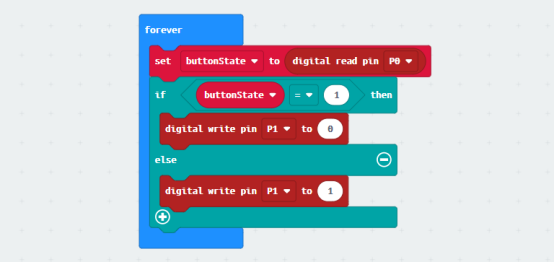
19.5.3 Learn the code program
The following instruction blocks will be applied in the program. Please see the description of the function as follows:
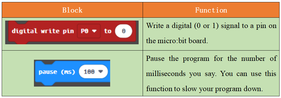
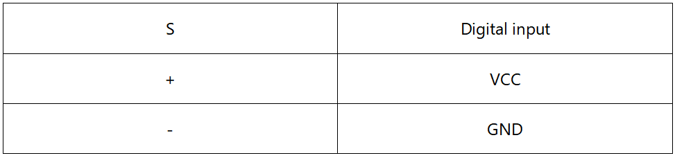
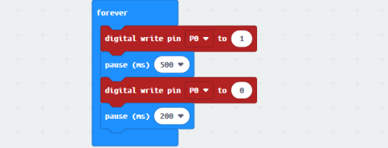
If you send a high level signal (indicated by 1) to the Active Buzzer through the  , the Active Buzzer will make a sound. In contrast, if you send a low level signal (indicated by 0) to the Active Buzzer, the Active Buzzer will be closed. If you continue to send these two signals in turn, the active buzzer will sound continuously.
19.6 Python programming
19.6.1 Run the program
1.Connect micro:bit and PC with a Micro USB cable.
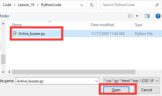
2. Open the Mu Editor installed on the computer, and click the button [Load] in the upper left corner to open the source code program of this lesson:

Find the code file for this lesson:
BBC_Microbit_Sensor\Code\Lesson_19\PythonCode
Select the file in ".py" format and click the Open:
3. Click the [Flash] button to download the program to Micro:bit, as shown in the following figure:
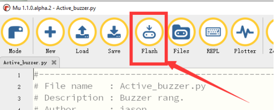
4.After the program is downloaded, if the Active Buzzer make a sound, it indicates the success of the experiment.

If you have problems, please send us an email: support@adeept.com
19.6.2 Learn the code program
You can send a high level signal (indicated by 1) to the Active Buzzer with the method of the pin0.write_digital(1) to enable the Active Buzzer to make a sound. In contrast, you can send a low level signal (indicated by 0) to the Active Buzzer to close it. If you continue to send these two signals in turn, the Active Buzzer will sound continuously.
10 11 12 13 14 | while True: pin0.write_digital(1) sleep(500) pin0.write_digital(0) sleep(200) |