In this lesson, we will carry out an interesting experiment on how to make a Flame Arrester.
41.1 Components to be prepared
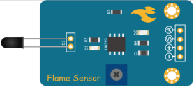
41.2 Flame Sensor
41.2.1 Flame Sensor
The flame sensor is a sensor specially used by the robot to search for the fire source,The flame sensor uses the characteristic that infrared rays are very sensitive to flames, uses a special infrared receiver tube to detect the flame, and then converts the brightness of the flame into high and low level signals, which are input to the central processing unit, and the central processing unit performs operations according to the changes in the signal. Corresponding program processing.
The Flame Sensor module can sense the flame. After the flame-sensitive diode is irradiated by the flame, the resistance changes, which in turn causes the voltage across the diode to change, generating an analog signal. At the same time, the analog signal is processed by a voltage comparator. When the analog signal exceeds a certain threshold, a corresponding alarm is issued.

41.2.2 Module features
1、Can detect flame or light source with wavelength in the range of 760 nm to 1100 nm. The larger the flame, the farther the test distance is.
2、The detection angle is about 60 degrees; Particularly sensitive to the flame spectrum.
3、Sensitivity is adjustable (adjusted by the blue digital potentiometer in the figure).
4、Comparator output, clear signal, good waveform, strong drive capability, over 15mA.
5、With adjustable precision potentiometer to adjust sensitivity.
6、Working voltage 3.3V-5V.
7、Output form: DO digital switch output (0 and 1) and AO analog voltage output.
8、With fixed bolt holes.

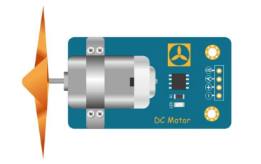
41.3 The DC Motor
41.3.1 The DC Motor
A DC motor is a motor that converts DC electrical energy into mechanical energy. Because of its good speed regulation performance, it is widely used in electric towing. DC motors are divided into three categories: permanent magnet, other excitation, and self-excitation according to the excitation mode. Self-excitation is divided into three types: parallel excitation, series excitation, and compound excitation.
When DC power is supplied to the armature winding through the brush, the N-pole conductor on the surface of the armature can flow current in the same direction.According to the left-hand rule, the conductor will be subjected to counterclockwise torque; a part of the conductor under the S pole of the armature surface also flow current in the same direction, and the conductor will also be subjected to a counterclockwise moment according to the left-hand rule. In this way, the entire armature winding, that is, the rotor will rotate counterclockwise, and the input DC energy is converted into mechanical energy output on the rotor shaft. It is composed of stator and rotor, stator: base, main magnetic pole, commutation pole, and brush device, etc. rotor (armature): armature core, armature winding, commutator, rotating shaft and fan, etc.
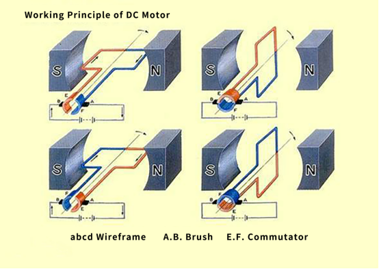
41.3.2 Working principle of the DC Motor
1.The DC power current flows along the positive pole of the power supply to the left brush. The brush and the commutator rub against each other. The current flows into the coil through the left commutator, flows out from the right side of the coil, and passes through the right commutator And the brush on the right flows back to the negative pole of the power supply, forming a closed loop.
2.Because the coil is in the magnetic field of the main magnetic pole, the coil will be subjected to the electromagnetic force. The two sides of the coil have different current directions (the current on the left flows inward and the right flows outward). Electromagnetic forces of the same magnitude and opposite directions, these two electromagnetic forces just form an electromagnetic torque. Under the pulling of the electromagnetic torque, the coil starts to rotate. In the DC motor, the coil is embedded in the rotor slot, and the motor starts to rotate.
3.The left and right commutator segments follow the shaft, and the brush is stationary. After one turn, the right coil reaches the left and the left coil reaches the right, but due to the presence of the commutator, it is now in the left coil The direction of the current flows in the same direction as the current changed by the coil on the left, so the direction of the electromagnetic force received does not change, and the same is true on the right. Therefore, from the perspective of space, the direction of the electromagnetic force received by the coil at the same position is always the same, which ensures the cyclic rotation of the motor.
4.But for a coil, because the magnetic field is different when the coil is turned to different positions, the electromagnetic force received by the coil is also constantly changing, so the coil turns unstable, suddenly and slowly. Therefore, you can install more coils to ensure that the coils are evenly and stably stressed.
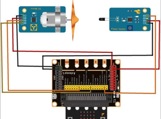
41.4 Circuit
You should connect the components according to the following circuit diagram, and view the pictures with the function “Zoom in”:
41.5 MakeCode programming
In the following part, we will make use of the online MakeCode editor to complete the experiment in this lesson.
41.5.1 Start programming
(1) Log in to the website
1. You need to enter the URL in the address bar of Google Browser:
https://makecode.microbit.org/
2. After the website is successfully opened, the interface as shown below will appear:

(2) Import a project
1. In the HOME interface, click the "Import" button to import the external ".hex" file:

In the pop-up dialog box, select the "Import File", as shown in the following figure:

Click the "Choose File"

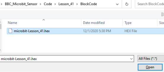
Find the code file for this lesson:
BBC_Microbit_Sensor\Code\Lesson_41\BlockCode
Select the file in ".hex" format and click the Open:
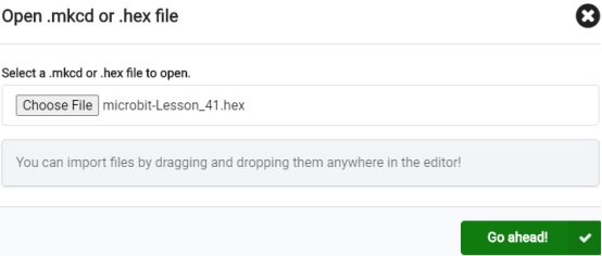
2. Notice whether the file has been loaded into the following window, and then click the "Go ahead!" button, as shown in the following figure:
3.You can see the following interface when successfully opening the file:
41.5.2 Run the program
1. After the program is written, connect micro:bit and PC with a Micro USB cable.
2. After micro:bit is connected to the computer, you need to first "Pair device". Click the  button on the right of
  in the lower left corner, and then click the
  option, as shown in the following figure:

Then click  in the lower right corner

Then the following dialog box will pop up, select  , and then click

After the device is successfully paired, the  button changes to

3. Start to download the program to the Micro:bit, click the button  , and the program will be downloaded directly to the Micro:bit. Then wait for the download completion. When the download is successful, your Micro:bit will restart and run the program you have downloaded before.
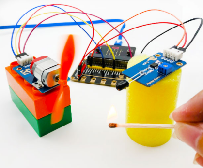
4.When the flame (lighter or match) is approaching Flame Sensor, DC motor rotates. When the flame is far away from the Flame Sensor, DC motor stops rotating.

[Note]
1.If no experimental phenomenon has been detected after clicking the button  , you need to click the
  button on the right of the
  , and then click the
  , as shown in the following figure:

2. If no experimental phenomenon is observed, you should check whether the USB cable of Micro:bit is successfully connected. If not, please download the program again.
3. The black probe of the flame sensor cannot be directly touched by the flame, otherwise the sensor will be damaged due to excessive heat, if the wind is not enough, you can connect an external power supply to the expansion board.
If you have problems, please send us an email: support@adeept.com
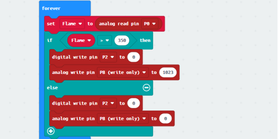
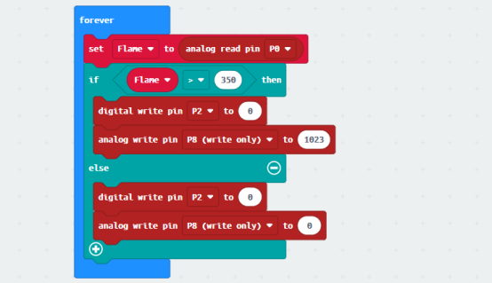
41.5.3 Learn the code program
The following instruction blocks will be applied in the program. Please see the description of the function as follows:
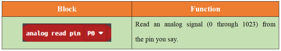
When the detected Flame is more than 350, DC Motor rotates. if not, DC Motor stops rotating.
41.6 Python programming
41.6.1 Run the program
1.Connect micro:bit and PC with a Micro USB cable.
2. Open the Mu Editor installed on the computer, and click the button [Load] in the upper left corner to open the source code program of this lesson:

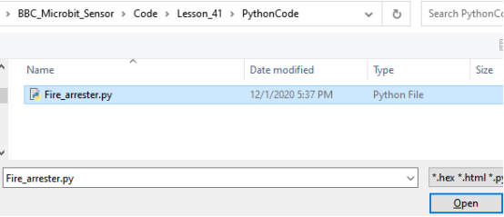
Find the code file for this lesson:
BBC_Microbit_Sensor\Code\Lesson_41\PythonCode
Select the file in ".py" format and click the Open:
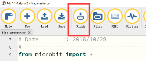
3. Click the button 【Flash】 and download the program to Micro:bit, as shown below:
4.After downloading the program successfully, when the flame (lighter or match) is approaching Flame Sensor, DC motor rotates. When the flame is far away from the Flame Sensor, DC motor stops rotating:
【Note】
The black probe of the flame sensor cannot be directly touched by the flame, otherwise the sensor will be damaged due to excessive heat, if the wind is not enough, you can connect an external power supply to the expansion board.
If you have problems, please send us an email: support@adeept.com
41.6.2 Learn the code program
The following is an explanation of the course code of this section.
(1)define Drive.
12 13 14 15 16 17 | def Drive(A): pin2.write_digital(0) if A < 0: pin3.write_digital(1) A = 1023 + A pin8.write_analog(A) |
(2)If the detected Flame is greater than 300, then control the DC Motor to rotate; on the contrary, control the DC Motor to stop rotating.
20 21 22 23 24 25 | while True: Flame = pin0.read_analog() if Flame > 300: Drive(1023) else: Drive(0) |