In this lesson, we will carry out an interesting experiment by programming on the Micro:bit so as to read the value of the rotary encoder.
34.1 Components to be prepared
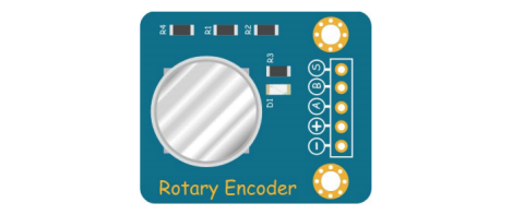
34.2 Rotary Encoder
34.2.1 Rotary Encoder
The rotary encoder is used to measure the speed and cooperate with the PWM technology to achieve fast speed regulation. The photoelectric rotary encoder can convert the mechanical displacements such as the angular displacement and angular velocity of the output shaft into corresponding electrical pulses through digital conversion (REP).In the course,we use incremental rotary encoders,which are rotary sensors that convert rotational displacement into a series of digital pulses. The rotation allows you to count the number of output pulses during forward and reverse rotation, and unlike potentiometers, there is no limit to this rotation counting. With the keys on the rotary encoder, it can be reset to the initial state, i.e. counting from 0.
34.2.2 Working principle of potentiometer
In the process of actual use, this encoder adopts the coaxial operation mode during operation, which means that the equipment can help the equipment to make better measurements through the shaft installation during operation. The purpose is to be able to achieve the same speed operation, so as to ensure more accurate data measurement. According to the different working principles of the rotary encoder, the output mode of the device is generally divided into two ways of single output and double output, each of which can be well adapted to different use characteristics. During the operation of the equipment, it is mainly measured by the corresponding pulse number, and the encoder is provided with the corresponding data by the phase difference between the angles.
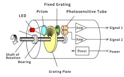
By a photoelectric code wheel with a shaft in the center, it has a ring-shaped, dark reticle, and is read by photoelectric transmitting and receiving devices to obtain four sets of sine wave signals combined into A, B, C, D, each sine wave The phase difference is 90 degrees (360 degrees relative to a cycle), the C and D signals are reversed and superimposed on the A and B phases to enhance the stable signal; another Z phase pulse is output per revolution to represent the zero reference Bit. Since the two phases of A and B differ by 90 degrees, the forward and reverse rotation of the encoder can be judged by comparing phase A or phase B. The zero reference position of the encoder can be obtained through the zero pulse.
The material of the encoder code disc is glass, metal and plastic. The glass code disc is a thin line deposited on the glass. It has good thermal stability and high precision. The metal code disc is directly engraved with or without engraved lines, which is not fragile. However, because the metal has a certain thickness, the accuracy is limited, and its thermal stability is an order of magnitude worse than that of glass. The plastic code wheel is economical and its cost is low, but the accuracy, thermal stability, and life span are all worse.
There are many optical channel engravings on the optical code disk of the absolute value rotary encoder, and each engraving in turn is arranged by 2 lines, 4 lines, 8 lines, 16 lines ... Each line is dark and dark, and a set of unique binary codes (Gray codes) from the 0th power of 2 to the n-1th power of 2 is obtained. This is called an n-bit absolute encoder. Such an encoder is determined by the mechanical position of the photoelectric code disc, and it is not affected by power outages and interference.
Each position determined by the mechanical position of the absolute rotary encoder is unique. It does not need to be memorized, it does not need to find a reference point, and it does not need to keep counting. When it is necessary to know the position and read its position whenever. In this way, the anti-interference characteristics of the encoder and the reliability of the data are greatly improved.
34.3 Low level and high level
In circuit, the form of binary (0 and 1) is presented as low level and high level.
Low level is generally equal to ground voltage (0V). High level is generally equal to the operating voltage of components.
The low level of Micro:bit is 0V and high level is 3.3V, as shown below. When IO port on Micro:bit outputs high level, low-power components can be directly driven,like LED.

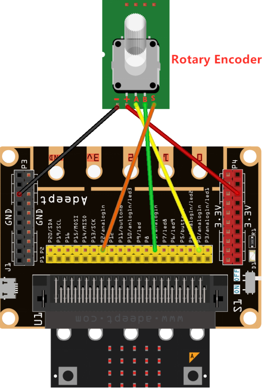
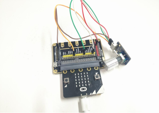
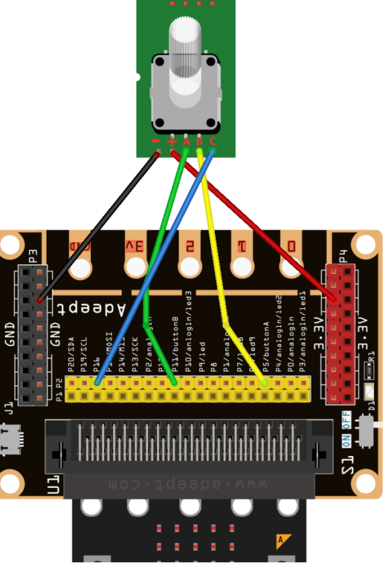
34.4 Circuit
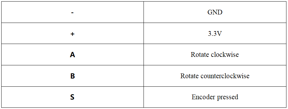
You should connect the components according to the following circuit diagram, and view the pictures with the function “Zoom in”:
34.5 MakeCode programming
Next, we will use the online MakeCode Editor to complete the experiment in this lesson.
34.5.1 Start programming
(1) Log in to the website
1. You need to enter the URL in the address bar of Google Browser:
https://makecode.microbit.org/
2. After the website is successfully opened, the interface as shown below will appear:

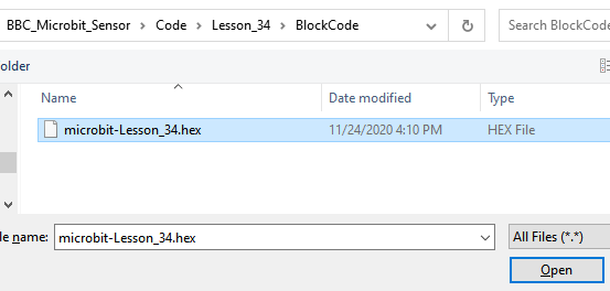
(2) Import a project
1. In the HOME interface, click the "Import" button to import the external ".hex" file:

In the pop-up dialog box, select the "Import File", as shown in the following figure:

Click the "Choose File"

Find the code file for this lesson:
BBC_Microbit_Sensor\Code\Lesson_34\BlockCode
Select the file in ".hex" format and click the Open:
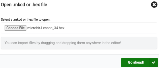
2. Notice whether the file has been loaded into the following window, and then click the "Go ahead!" button, as shown in the following figure:
3.You can see the following interface when successfully opening the file:
34.5.2 Run the program
1. After the program is written, connect micro:bit and PC with a Micro USB cable.
2. After micro:bit is connected to the computer, you need to first "Pair device". Click the  button on the right of
  in the lower left corner, and then click the
  option, as shown in the following figure:

Then click  in the lower right corner

Then the following dialog box will pop up, select  , and then click

After the device is successfully paired, the  button changes to

3. Start to download the program to Micro:bit, and click the  button. Generally, the program will be downloaded directly to the Micro:bit. After the download is completed, your Micro:bit will restart and run the program just downloaded. as shown below:
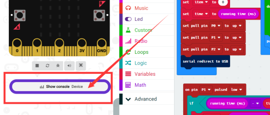
4.Rotate the encoder clockwise or counterclockwise and click the button 【Show console Device】on the left, as shown below:
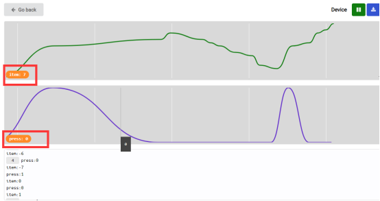
5.The following waveform diagram can be seen.  represents the analog value of the rotary encoder when rotating clockwise or counterclockwise. Rotate clockwise, and the analog value of
  will become larger.Rotate counterclockwise, and the analog value of
  will become smaller.
  represents the button state of the rotary encoder.Press the rotary encoder,and
  will change into
  .Rotate the encoder, and
  will change into
  :
:
[Note]
1.If no experimental phenomenon has been detected after clicking the button  , you need to click the
  button on the right of the
  , and then click the
  , and observe the【Show console Device】again, as shown in the following figure:

2. If no experimental phenomenon is observed, you should check whether the USB cable of Micro:bit is successfully connected. If not, please download the program again.
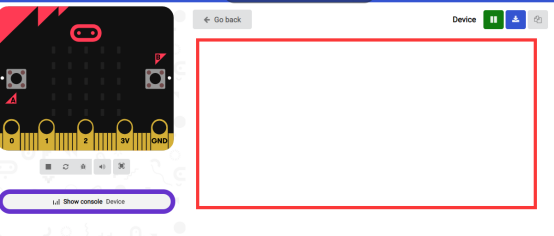
3.After clicking the button 【Show console Device】 on the left, if no waveform is shown on the right, please rotate the encoder again, and you will see the waveform. If no waveform has been shown yet, please repeat the above steps.
4.After clicking the button  , if the button
  isn’t shown on the left, please rotate the encoder, and the button
  will show on the left.
If you have problems, please send us an email: support@adeept.com
34.5.3 Learn the code program
The following instruction blocks will be applied in the program. Please see the description of the function as follows:
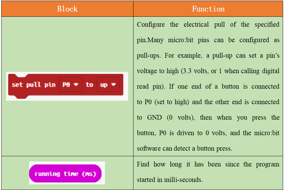
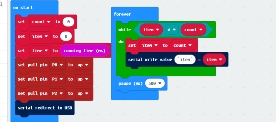
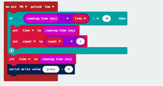
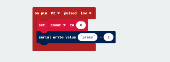
(1)When rotating the encoder counterclockwise, reduce 1 from the analog count, and change the【press】of recording button state to 0 simultaneously.
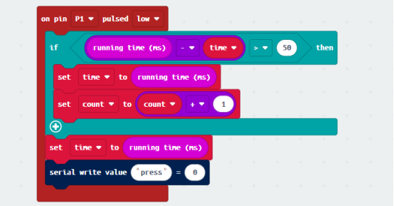
(2)When rotating the encoder clockwise, please add 1 to the analog count and change the【press】of recording button state to 0 simultaneously.
(3) When pressing the rotary encoder, please set the count to 0 and change the【press】of recording button state to 1.
34.6 Python programming
34.6.1 Circuit
You should connect the components according to the following circuit diagram, and view the pictures with the function “Zoom in”:
34.6.2 Run the program
1.Connect micro:bit and PC with a Micro USB cable.
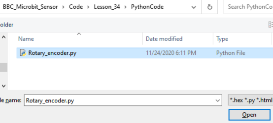
2. Open the Mu Editor installed on the computer, and click the button [Load] in the upper left corner to open the source code program of this lesson:

Find the code file for this lesson:
BBC_Microbit_Sensor\Code\Lesson_34\PythonCode
Select the file in ".py" format and click the Open:
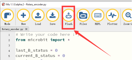
3.Click button【Flash】 to download the program to the Micro:bit. Click the button  immediately (click the button
  when the Micro:bit indicator is flashing), and the output data will be read on the console, as shown below:
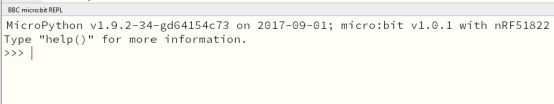
After downloading the program to Micro:bit successfully, click the button  , and it will be blank on the console:
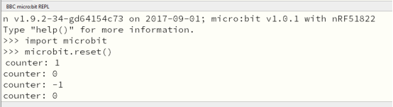
4.Rotate the encoder clockwise or counterclockwise, and the encoder value will be output on the console, as shown below:
【Note】
1. If no value can be read on the console when rotating the encoder, please check whether the wiring of the rotary encoder is connected or not.
2. If no value can be read on the console, please click the button 【Flash】 again, click the button  immediately, and rotate the encoder. If no data are output, please repeat the above steps or check whether the wiring is connected correctly.
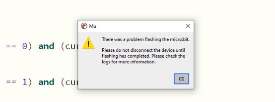
3. If the following prompt shows, please connect the Micro:bit USB cable and download the program again.
4. After clicking the button  , the information will be shown on the console as follows. If no data is output when rotating the encoder,please click
  again. When the indicator light of Micro:bit stops flashing, click the button
  again.
If you have problems, please send us an email: support@adeept.com
34.6.2 Learn the code program
The description of the course code in this section is as follows.
(1) Determine whether the rotating shaft of the rotary encoder is rotating. If it rotates, mark this state as 0 with flag.
15 16 17 18 | last_B_status = pin11.read_digital() while (not pin5.read_digital()): current_B_status = pin11.read_digital() flag = 0 |
(2) If the rotary encoder rotates, determine the rotation direction from state 0 to state 1 with if (last_B_status == 0) and (current_B_status == 1), and it rotates counterclockwise, counter-1.Determine the rotation direction from state 1 to state 0 with if (last_B_status == 0) and (current_B_status == 1), and it rotates counterclockwise, counter+1.
1 2 3 | if flag == 0: flag = 1 if (last_B_status == 0) and (current_B_status == 1): counter -= 1 if (last_B_status == 1) and (current_B_status == 0): counter += 1 |