In this lesson, we will carry out an interesting experiment by programming on the Micro:bit so as to switch on LED.
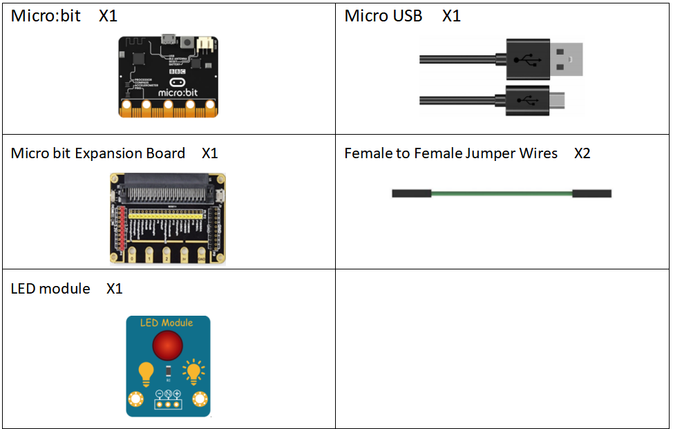
16.1 Components to be prepared
16.2 The LED module
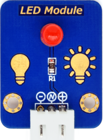
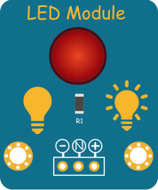
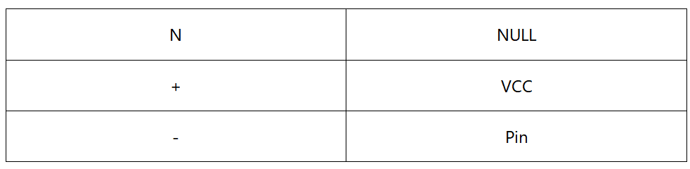
16.2.1 LED module
The LED is the abbreviation of light emitting diode. It is usually made of gallium arsenide, gallium phosphide semiconductor materials. The LED has two electrodes, a positive electrode and a negative electrode, it will light only when a forward current passes, and it can be red, blue, green or yellow light, etc. The color of light depends on the materials it was made.
In general, the drive current for LED is 5-20mA. Therefore, in reality it usually needs an extra resistor for current limitation so as to protect the LED.
16.2.2 What is resistor?
The main function of the resistor is to limit current. In the circuit, the character ‘R’ represents resistor, and the unit of resistor is ohm(Ω).
The band resistor is used in this experiment. A band resistor is one whose surface is coated with some particular color through which the resistance can be identified directly. The LED module we used in this lesson is SMD resistor. We soldered it directly to the pcb board. As is shown below:
16.3 Low level and high level
In circuit, the form of binary (0 and 1) is presented as low level and high level.
Low level is generally equal to ground voltage (0V). High level is generally equal to the operating voltage of components.
The low level of Micro:bit is 0V and high level is 3.3V, as shown below. When IO port on Micro:bit outputs high level, low-power components can be directly driven,like LED.

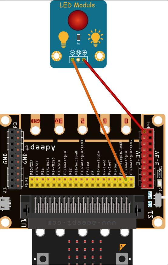
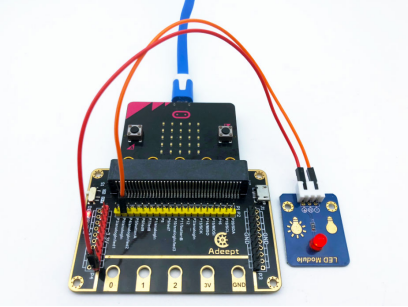
16.4 Circuit
You need to connect the components according to the circuit diagram below.
16.5 MakeCode programming
Next, we will use the online MakeCode Editor to complete the experiment in this lesson.
16.5.1 Start programming
(1) Log in to the website
1. You need to enter the URL in the address bar of Google Browser:
https://makecode.microbit.org/
2. After the website is successfully opened, the interface as shown below will appear:

(2) Import a project
1. In the HOME interface, click the "Import" button to import the external ".hex" file:

In the pop-up dialog box, select the "Import File", as shown in the following figure:

Click the "Choose File"

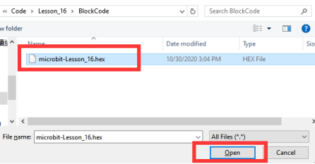
Find the code file for this lesson:
BBC_Microbit_Sensor\Code\Lesson_16\BlockCode
Select the file in ".hex" format and click the Open:
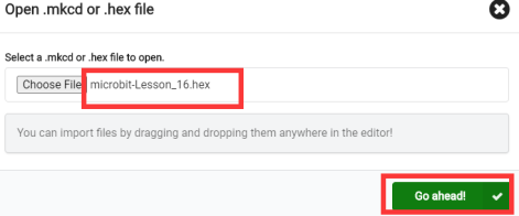
2. Notice whether the file has been loaded into the following window, and then click the "Go ahead!" button, as shown in the following figure:
3.You can see the following interface when successfully opening the file:
16.5.2 Run the program
1. After the program is written, connect micro:bit and PC with a Micro USB cable.
2. After micro:bit is connected to the computer, you need to first "Pair device". Click the  button on the right of
  in the lower left corner, and then click the
  option, as shown in the following figure:

Then click  in the lower right corner

Then the following dialog box will pop up, select  , and then click

After the device is successfully paired, the  button changes to

3. Start to download the program to Micro:bit, and click the  button. Generally, the program will be downloaded directly to the Micro:bit. After the download is completed, your Micro:bit will restart and run the program just downloaded.Pay attention to LED and see whether it is on, as shown below:
[Note]
If Micro:bit doesn't respond after clicking the  , you need to click the
  button on the right of the
  , and then click the
  , and observe the situation of the Micro:bit again, as shown in the following figure:

If you have problems, please send us an email: support@adeept.com
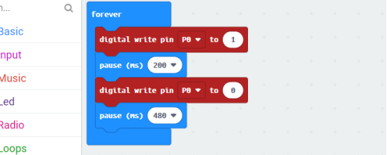
16.5.3 Learn the code program
The following instruction blocks will be applied in the program. Please see the description of the function as follows:
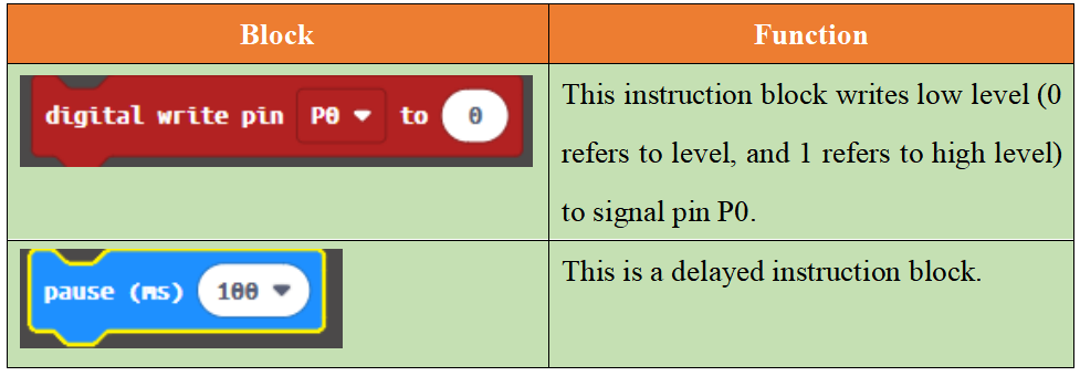
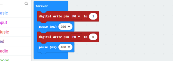
(1)In the code, write 1 to the P0 port to turn ON the LED. After waiting for 200ms, write 0 to the P0 port to turn OFF the LED.After waiting for 480ms, the LED will be turned ON again. Repeat the loop, then LED will start blinking.
16.6 Python programming
16.6.1 Run the program
1.Connect micro:bit and PC with a Micro USB cable.
2. Open the Mu Editor installed on the computer, and click the button [Load] in the upper left corner to open the source code program of this lesson:

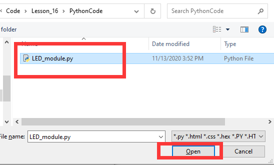
Find the code file for this lesson:
BBC_Microbit_Sensor\Code\Lesson_16\PythonCode
Select the file in ".py" format and click the Open:
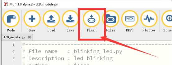
3. Click the [Flash] button to download the program to Micro:bit, as shown in the following figure:
4. After successfully downloading the program, when LED is on, it suggests that the experiment is a success.
If you have problems, please send us an email: support@adeept.com
16.6.2 Learn the code program
In the code, write 1 to the P0 port to turn ON the LED. After waiting for 200ms, write 0 to the P0 port to turn OFF the LED.After waiting for 480ms, the LED will be turned ON again. Repeat the loop, then LED will start blinking.
9 10 11 12 13 14 15 | from microbit import *
while True: pin0.write_digital(1) sleep(200) pin0.write_digital(0) sleep(480) |