In this lesson, we will carry out an interesting experiment by programming on the Micro:bit so as to control WS2812 RGB ring with Ultrasonic.
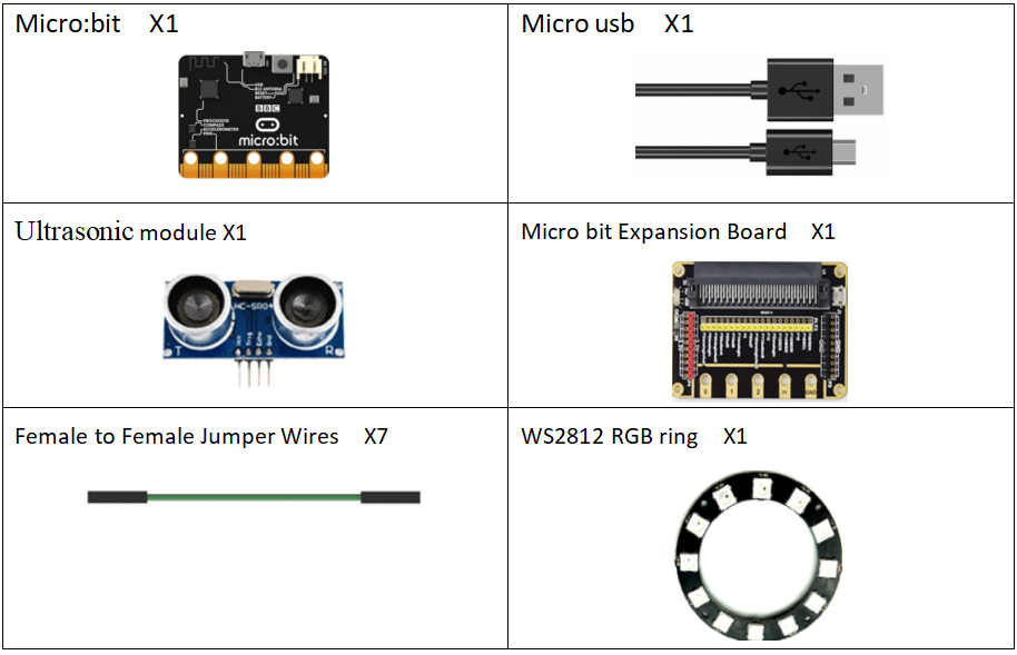
33.1 Components to be prepared
33.2 The introduction of the WS2812 RGB ring
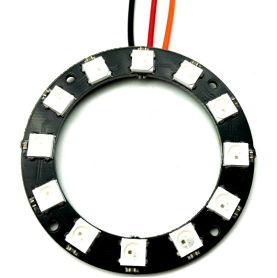
33.2.1 The WS2812 RGB ring
WS2812 RGB ring is an intelligent external control LED light source integrating control circuit and light-emitting circuit. Its shape is the same as a 5050 LED bead, and each component is a pixel. The pixel includes the intelligent interface, data latch signal, shaping and amplifying driving circuit and the anti-reverse circuit. It also includes a high-precision internal oscillating circuit and a high-precision constant current control module, which effectively ensures the high consistence of the color of the pixel. And it has a unique breakpoint retransmission function, and exerts two-way signal transmission. The overall color display will not be affected even with single pixel damage.
The data protocol adopts the single NZR communication mode. After the power-on reset, the DIN terminal accepts the data transmitted from the controller. The first 24-bit data is extracted by the first pixel and sent to the data latch in the internal of the pixel. The remaining data is shaped and amplified by the internal shaping processing circuit and then transferred and output to the next cascaded pixel through the DO port. And the signal is reduced by 24 bits every time a pixel is transmitted. The pixel adopts automatic shaping and forwarding technology, so that the number of cascaded pixels is not limited by signal transmission, and only requires signal transmission speed.
After receiving the data and reduced by 24bit, the DIN terminal compares with the DIN data. If there is no signal at the DIN terminal, the DIN terminal receives the signal and loops to the BIN terminal to accept the input signal, ensuring that the damage of one of the ICs does not affect the cascaded transmission and the control IC remains in the BIN port acceptance state until the next power-on to reconfirm after power-off.
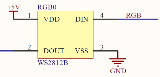
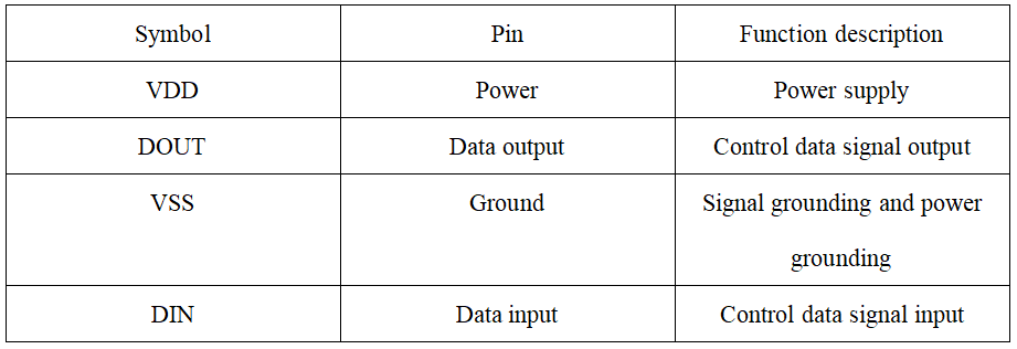
Function of the pins:
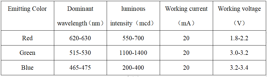
LED characteristic parameter
LED pin:
The LED circle we use in this experiment is as follow:

33.3 Low level and high level
In circuit, the form of binary (0 and 1) is presented as low level and high level.
Low level is generally equal to ground voltage (0V). High level is generally equal to the operating voltage of components.
The low level of Micro:bit is 0V and high level is 3.3V, as shown below. When IO port on Micro:bit outputs high level, low-power components can be directly driven,like LED.

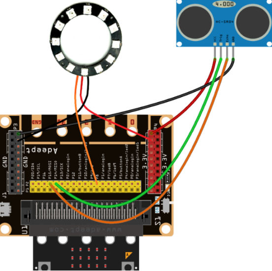
33.4 Circuit
You should connect the components according to the following circuit diagram. View the pictures with the function “Zoom in” when the pin "DI" of the WS2812 RGB ring is connected to the pin P8 on the Micro bit Expansion Board:
33.5 MakeCode programming
Next, we will use the online MakeCode Editor to complete the experiment in this lesson.
33.5.1 Start programming
(1) Log in to the website
1. You need to enter the URL in the address bar of Google Browser:
https://makecode.microbit.org/
2. After the website is successfully opened, the interface as shown below will appear:

(2) Import a project
1. In the HOME interface, click the "Import" button to import the external ".hex" file:

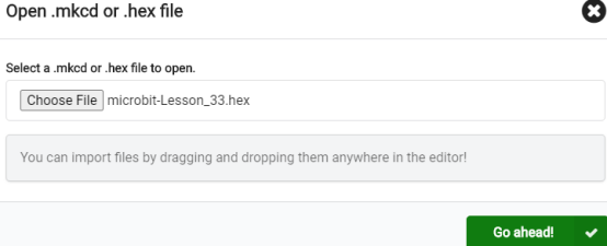
In the pop-up dialog box, select the "Import File", as shown in the following figure:

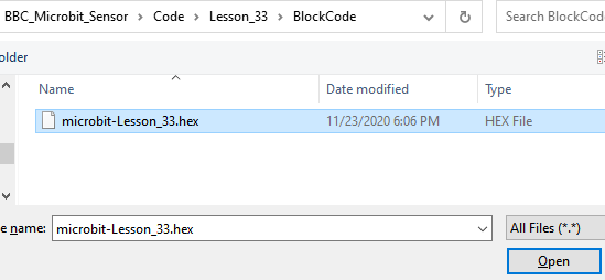
Click the "Choose File"

Find the code file for this lesson:
BBC_Microbit_Sensor\Code\Lesson_33\BlockCode
Select the file in ".hex" format and click the Open:
2. Notice whether the file has been loaded into the following window, and then click the "Go ahead!" button, as shown in the following figure:
3.You can see the following interface when successfully opening the file:
33.5.2 Run the program
1. After the program is written, connect micro:bit and PC with a Micro USB cable.
2. After micro:bit is connected to the computer, you need to first "Pair device". Click the  button on the right of
  in the lower left corner, and then click the
  option, as shown in the following figure:

Then click  in the lower right corner

Then the following dialog box will pop up, select  , and then click

After the device is successfully paired, the  button changes to

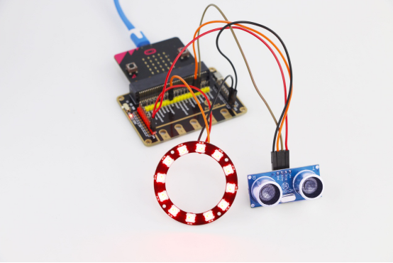
3. Start to download the program to Micro:bit, and click the  button. Generally, the program will be downloaded directly to the Micro:bit. After the download is completed, your Micro:bit will restart and run the program just downloaded. The WS2812 RGB ring will light up in different colors, if an object is approaching the ultrasonic sensor, as shown below:

[Note]
1.If no experimental phenomenon has been detected after clicking the button  , you need to click the
  button on the right of the
  , and then click the
  , and observe the WS2812 RGB ring again, as shown in the following figure:

2. If no experimental phenomenon is observed, you should check whether the USB cable of Micro:bit is successfully connected. If not, please download the program again.
If you have problems, please send us an email: support@adeept.com
33.5.3 Learn the code program
The following instruction blocks will be applied in the program. Please see the description of the function as follows:
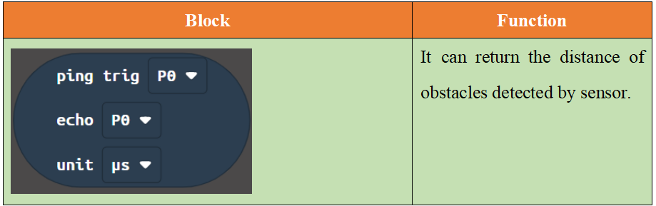
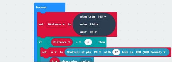
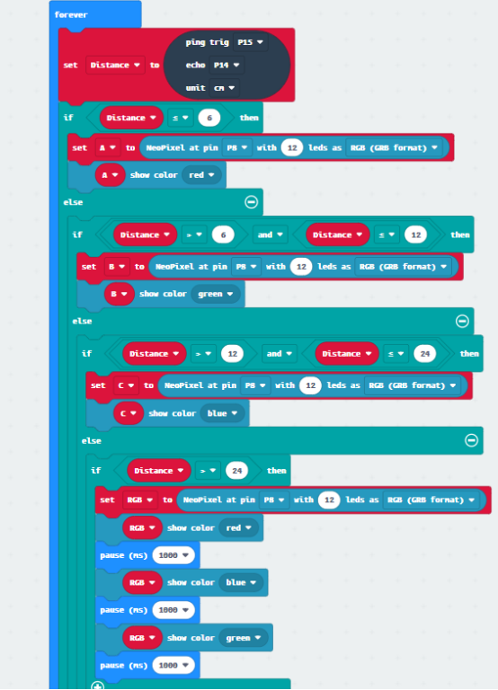
Read the data of the ultrasonic sensor firstly. This data is about the distance of the obstacle detected by the ultrasonic sensor. If the distance of the detected obstacle is ≤ 6cm, the red LED controlling WS2812 RGB ring will light up. If the distance of the detected obstacle is > 6cm and ≤ 12cm, the green LED controlling WS2812 RGB ring will light up. If the distance of the detected obstacle is > 12cm and ≤ 24cm, the blue LED controlling WS2812 RGB ring will light up. If the distance of the detected obstacle is > 24cm, the red , blue and green LEDs controlling WS2812 RGB ring will light up.
【Note】
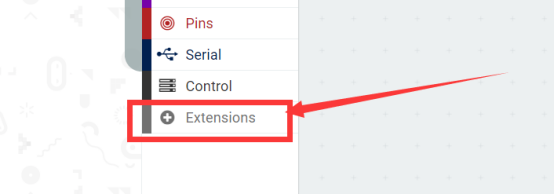
If you want to import the “Neopixel” expansion block in a new project, follow the steps below to add it.
(1)Click the button【Extensions】:
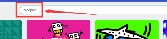
(2)Enter “Neopixel”and click search.
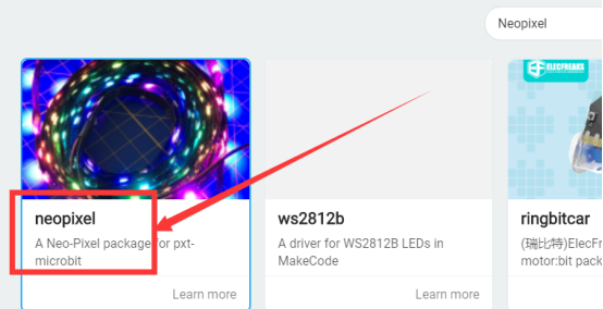
(3)Select Select "Neopixel":
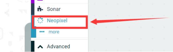
(4) Added successfully:
33.6 Python programming
33.6.1 Run the program
1.Connect micro:bit and PC with a Micro USB cable.
2. Open the Mu Editor installed on the computer, and click the button [Load] in the upper left corner to open the source code program of this lesson:

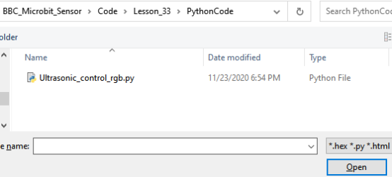
Find the code file for this lesson:
BBC_Microbit_Sensor\Code\Lesson_33\PythonCode
Select the file in ".py" format and click the Open:
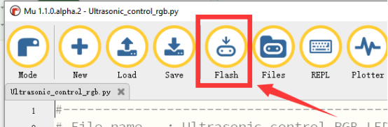
3.Click the button 【Flash】and download the program to Micro:bit, as shown below:
4.When the download is successful, the WS2812 RGB ring will light up in different colors, if an object is approaching the ultrasonic sensor, as shown below:
If you have problems, please send us an email: support@adeept.com
33.6.2 Learn the code program
(1) Obtain the data of the ultrasonic sensor, and calculate the distance of the obstacle.
18 19 20 21 22 23 24 25 26 27 28 33 33 31 33 33 34 35 36 37 38 39 40 41 42 43 44 45 | def distance_mm(self): spi.init(baudrate=115200, sclk=self.sclk_pin, mosi=self.trigger_pin, miso=self.echo_pin) pre = 0 post = 0 k = -1 length = 500 resp = bytearray(length) resp[0] = 0xFF spi.write_readinto(resp, resp) # find first non zero value try: i, value = next((ind, v) for ind, v in enumerate(resp) if v) except StopIteration: i = -1 if i > 0: pre = bin(value).count("1") # find first non full high value afterwards try: k, value = next((ind, v) for ind, v in enumerate(resp[i:length - 2]) if resp[i + ind + 1] == 0) post = bin(value).count("1") if k else 0 k = k + i except StopIteration: i = -1 dist = -1 if i < 0 else round((pre + (k - i) * 8. + post) * 8 * 0.172) return dist |
(2) Read the data of the ultrasonic sensor firstly. This data is about the distance of the obstacle detected by the ultrasonic sensor. If the distance of the detected obstacle is ≤ 6cm, the red LED controlling WS2812 RGB ring will light up. If the distance of the detected obstacle is > 6cm and ≤ 12cm, the green LED controlling WS2812 RGB ring will light up. If the distance of the detected obstacle is > 12cm and ≤ 24cm, the blue LED controlling WS2812 RGB ring will light up. If the distance of the detected obstacle is > 24cm, the red , blue and green LEDs controlling WS2812 RGB ring will light up.
65 66 67 68 69 70 71 72 73 74 75 76 77 78 79 | while True: distance = round(sonar.distance_mm()/10) if distance < 6.0: LightAll(red) if distance > 6.0 and distance < 12: LightAll(green) if distance > 12.0 and distance < 24: LightAll(blue) if distance > 24.0: LightAll(red) sleep(1000) LightAll(green) sleep(1000) LightAll(blue) sleep(1000) |