In this lesson, we will carry out an interesting experiment by programming on the Micro:bit so as to measure distance with Ultrasonic Module.
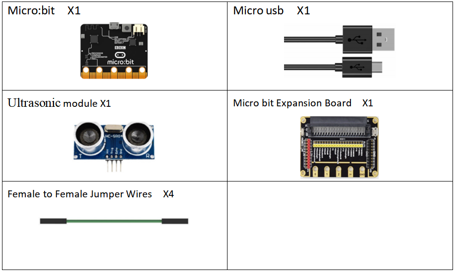
30.1 Components to be prepared
30.2 Ultrasonic distance sensor
30.2.1 Ultrasonic distance sensor
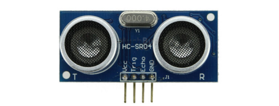
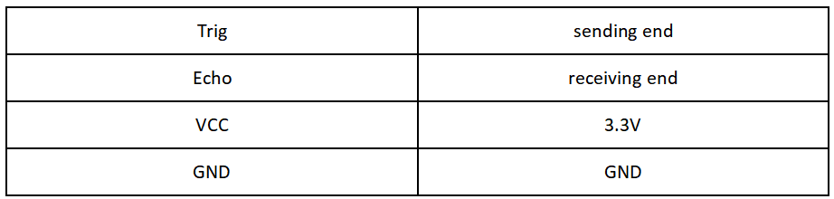
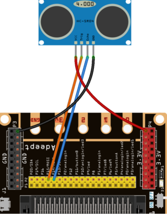
The model of the ultrasonic distance sensor we use is hc-sr04, it is mainly composed of two left and right probes, looking like our human eyes. One probe is responsible for transmitting sound waves for detection, and the other probe is responsible for receiving sound waves for return. It has 4 pins, which are VCC; Trig (control end - trigger signal input); Echo (receiver - recovery signal output); Gnd(ground).
30.2.2 The working principle of the Ultrasonic Distance Sensor
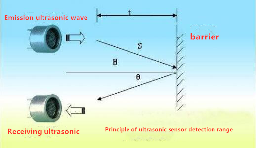
The method of detecting distance of ultrasonic wave is called echo detection method,which ultrasonic emitter emits to a certain direction, in the moment of timer timing starts at the same time, the ultrasonic wave in air, run into obstacles on the way your face (objects) block was reflected immediately, ultrasonic receiver received the ultrasonic reflected back to immediately stop timing. The propagation speed of ultrasonic wave in the air is 340m/s. According to the time t recorded by the timer, the distance s from the launch point to the obstacle surface can be calculated, that is, s=340t/2. Under this principle of ultrasound, ultrasonic ranging module is widely used in practical applications, such as car reversing radar, uav, and intelligent car.
30.3 Low level and high level
In circuit, the form of binary (0 and 1) is presented as low level and high level.
Low level is generally equal to ground voltage (0V). High level is generally equal to the operating voltage of components.
The low level of Micro:bit is 0V and high level is 3.3V, as shown below. When IO port on Micro:bit outputs high level, low-power components can be directly driven,like LED.

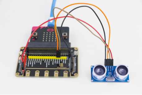
30.4 Circuit
You should connect the components according to the following circuit diagram, and view the pictures with the function “Zoom in”: The pin Echo is connected to P14; the pin Trig is connected to P15.
30.5 MakeCode programming
Next, we will use the online MakeCode Editor to complete the experiment in this lesson.
30.5.1 Start programming
(1) Log in to the website
1. You need to enter the URL in the address bar of Google Browser:
https://makecode.microbit.org/
2. After the website is successfully opened, the interface as shown below will appear:

(2) Import a project
1. In the HOME interface, click the "Import" button to import the external ".hex" file:

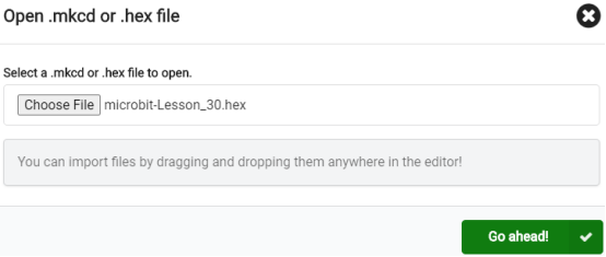
In the pop-up dialog box, select the "Import File", as shown in the following figure:

Click the "Choose File"

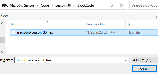
Find the code file for this lesson:
BBC_Microbit_Sensor\Code\Lesson_30\BlockCode
Select the file in ".hex" format and click the Open:
2. Notice whether the file has been loaded into the following window, and then click the "Go ahead!" button, as shown in the following figure:
3.You can see the following interface when successfully opening the file:

30.5.2 Run the program
1. After the program is written, connect micro:bit and PC with a Micro USB cable.
2. After micro:bit is connected to the computer, you need to first "Pair device". Click the  button on the right of
  in the lower left corner, and then click the
  option, as shown in the following figure:

Then click  in the lower right corner

Then the following dialog box will pop up, select  , and then click

After the device is successfully paired, the  button changes to

3. Start to download the program to Micro:bit, and click the  button. Generally, the program will be downloaded directly to the Micro:bit. After the download is completed, your Micro:bit will restart and run the program just downloaded. as shown below:

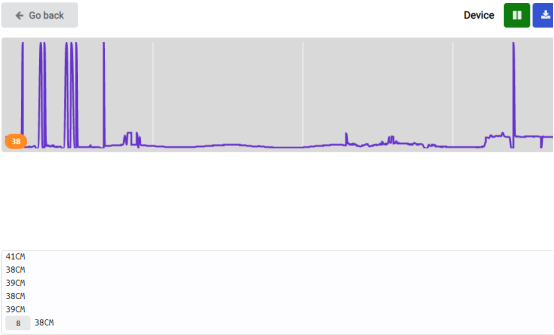
4. Then click 【Show console Device】:
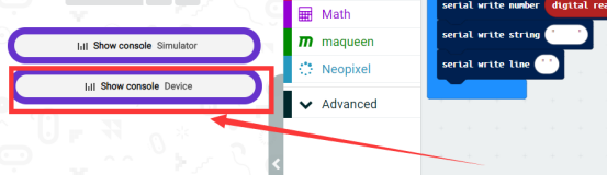
The distance data can be detected by the Ultrasonic module:
[Note]
1.If no experimental phenomenon has been detected after clicking the button  , you need to click the
  button on the right of the
  , and then click the
  , and open the 【Show console Device】 again, as shown in the following figure:

2. If no experimental phenomenon is observed, you should check whether the USB cable of Micro:bit is successfully connected. If not, please download the program again.
If you have problems, please send us an email: support@adeept.com
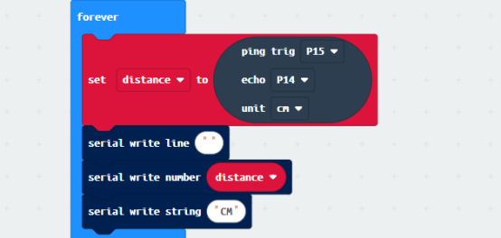
30.5.3 Learn the code program
The following instruction blocks will be applied in the program. Please see the description of the function as follows:
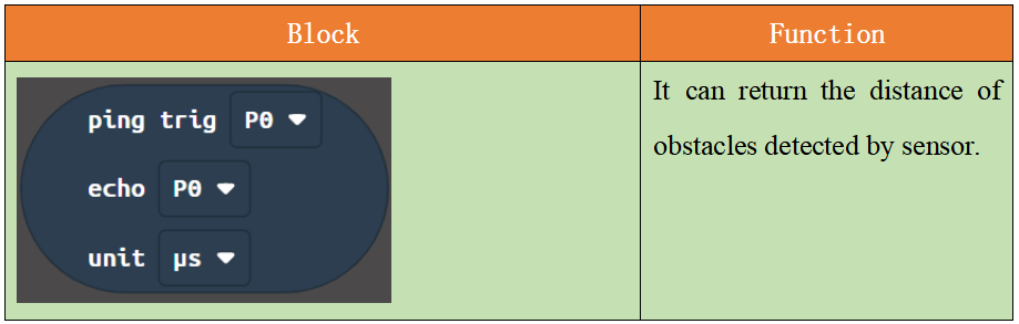
The distance of obstacles measured by the ultrasonic module will be assigned to the variable distance.
【Note】
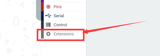
If you want to import the “Sonar” expansion block in a new project, follow the steps below to add it.
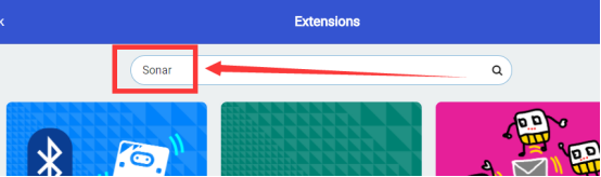
(1)Click the button【Extensions】:
(2)Enter “Sonar”and click search.
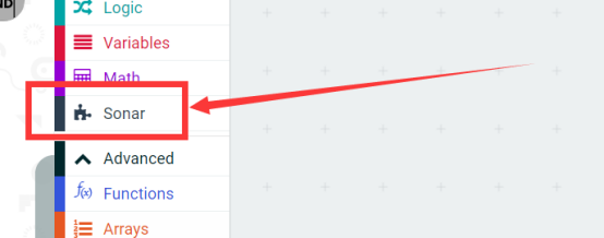
(3)Select “Sonar”.
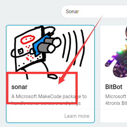
(4) Added successfully:
30.6 Python programming
30.6.1 Run the program
1.Connect micro:bit and PC with a Micro USB cable.
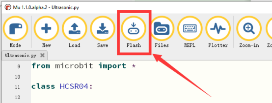
2. Open the Mu Editor installed on the computer, and click the button [Load] in the upper left corner to open the source code program of this lesson:

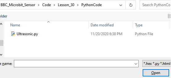
Find the code file for this lesson:
BBC_Microbit_Sensor\Code\Lesson_30\PythonCode
Select the file in ".py" format and click the Open:
3.Click button【Flash】 to download the program to the Micro:bit. Click the button  immediately (click the button
  when the Micro:bit indicator is flashing), and the output data will be read on the console, as shown below:
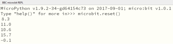
4.After successfully downloading the program, click the button 【REPL】 on the Mu editor. The distance data detected by the Ultrasonic module can be read in the console. -0.1 represents no obstacles have been detected:
【Note】
Click the button【Flash】 again, if no data can be read on the console. Click the button  immediately (click the button
  when the Micro:bit indicator is flashing). Repeat the above steps or check whether the wiring is successfully connected, if no data are output, as shown below:
5. As shown below:
If you have problems, please send us an email: support@adeept.com
30.6.2 Learn the code program
The description of the course code in this section is as follows.
(1) Obtain the data of the ultrasonic sensor, and calculate the distance to the obstacle.
18 19 20 21 22 23 24 25 26 27 28 30 30 31 32 33 34 35 36 37 38 39 40 41 42 43 44 45 | def distance_mm(self): spi.init(baudrate=115200, sclk=self.sclk_pin, mosi=self.trigger_pin, miso=self.echo_pin) pre = 0 post = 0 k = -1 length = 500 resp = bytearray(length) resp[0] = 0xFF spi.write_readinto(resp, resp) # find first non zero value try: i, value = next((ind, v) for ind, v in enumerate(resp) if v) except StopIteration: i = -1 if i > 0: pre = bin(value).count("1") # find first non full high value afterwards try: k, value = next((ind, v) for ind, v in enumerate(resp[i:length - 2]) if resp[i + ind + 1] == 0) post = bin(value).count("1") if k else 0 k = k + i except StopIteration: i = -1 dist = -1 if i < 0 else round((pre + (k - i) * 8. + post) * 8 * 0.172) return dist |
(2) Print out the read data of the ultrasonic sensor.
48 49 50 | while True: print('%.1f' % (sonar.distance_mm()/10)) sleep(1000) |